
To layout the helix parts you will absolutely need a protractor of some kind. I use a draftsman's tool, an adjustable triangle. Since I was a draftsmen in my first career, I already own one. If you need one they can be purchased at Hobby Lobby, maybe Office Max/Office Depot (and other fine drafting equipment stores).
 |
| Adjustable Triangle |
I purchased my plywood at a Lowes store (I'm a diehard Lowes customer) in 4' x 8' sheets and had Lowes cut them in half. They have that big vertical widget they use for cutting, I don't (wish I did). Because of the size of the thing it's far more accurate than any table saw I ever owned. Besides, cuts are free.
So now I have a pile of 4' x 4' squares. Half of them are not exactly 48" square. The saw "kerf", or thickness of the blade, may take an 1/8" or more out of the panel. It's not really an issue since we are not relying on the dimensions.
After you get the panels home, the first thing to do (if you're not asked to do something else) is layout the pertinent dimensions. All the steps in the following paragraphs need only be done to one of the plywood sheets. To make the helix parts as accurate as you can you must put them all in a stack and line up the outer edges as best as possible. Some panels will be slightly shorter because of the cuts at the store, but all the panels will probably be a consistent width. Rather than drill and cut each panel separately, you'll want to "gang cut" all the panels at once. Any thing done to the uppermost panel will happen to all the others and ensure accurate fit of the helix parts.
The first step in laying out the panels is to choose one to do the layout on. Use the one that is closest to 48" square. It will make the layout phase easier. Then find the center of that panel...
 |
| "find the center of that panel" |
Now that we know where the center is we need to make two lines perpendicular to each other (the angle between these two lines should be 90°). If the panel was truly 48" square, this may already be done. If not draw a new line at an angle 90° from either line. Make sure you note which two lines are perpendicular. These will be your base lines and a lot of the rest of the layout depends on those two...
 |
| "the angle between these two lines should be 90°" |
 |
| "The number of support posts...determines the radial separation of the post centers." |
 |
| "I move the triangle...draw another line at 22.5° |
 |
| "I do the same thing to each...perpendicular line" |
I keep repeating this procedure using any of the lines until I have 16 individual lines separated by 22.5°...
 |
| "16 individual lines separated by 22.5°" |
I now have all the radial centers required for all the posts holes. Now we need to locate the post holes relative to the center of the panel. First you need to decide how far you want the posts to sit from the center and the distance between each post in each set. This dimension is determined by the radius of any curves you intend to create, the distance between multiple tracks if needed and the clearance between outside rail and the posts. Be generous with any clearances, too tight and you'll have cars and locomotives crashing into things. Trust me, I know from experience...
 |
| "decide how far you want the posts...from the center and the distance between each post" |
Once that's decided you can draw the concentric circles that will locate the post holes. There a few different ways to do this. You can use a straight edge and measure the post centers on each radial line. If you have (or can find) one of those big beam compasses you can set that to the correct distances and draw concentric circles...
 |
| Real Beam Compass |
 |
| DIY Beam Compass |
Whichever method you use to draw the circles, the post center will be located where ever the radial lines intersect the pertinent circles. Once this is accomplished you're set to start the machine work.
Get out a drill, a drill bit, a screwdriver bit (phillips head) and a box of drywall screws. If you don't have a drill borrow one from your mother, kid sister, neighbor or people you meet on the street. A hand screwdriver is not gonna work. Not fast enough for one, but also a LOT more work. If you don't have drywall screws than you are missing out on THE most important invention in history. Dry wall screws are the mechanical equivalent of duct tape. Between the two you can fix (or build) almost everything. Drywall screws come in a variety of lengths from about 3/4" to 3". The size you want depends on the thickness of your plywood and the number of panels.
Anyway...Stack all the plywood panels as straight as they can be. Once they are all stacked neatly take the drywall screws and screw the four corners together. You want the screws tight, but not enough to damage the plywood. If you feel you need more add screws halfway between the first four along the side of the panels.
Load the drill bit into the drill. The size of the bit is determined by the diameter of the posts you intend to use. I used 1/2" diameter dowels, so I used a 1/2" diameter bit. Although you can use any drill bit, the bit should be a type made for cutting wood. The points on these bits make it easier to center the bit on your markings...
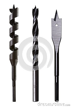 |
| Drill Bits For Wood |
Almost forgot...The hole in the center of the panels should be a diameter that accepts a pretty hefty bolt. I used a 1/2" diameter bolt and used a corresponding drill size. This bolt will be used as a pivot for any cutting guides you use to cut the helix levels. I should have mentioned it can also be used as a pivot for any DIY compass you conjure up.
Starting with the center point hold the drill perpendicular to the panels and drill ALL the way through the stack. Repeat this for each center mark keeping the drill at a vertical right angle to the stack of plywood. If your drill has a level in the casing use that, but keep checking that the drill is vertically straight. Any deviation will show up when you try to fit your posts through the holes. The more levels you are using the more that discrepancy will affect the fit of the parts. Too far from vertical and you will start cracking (if not breaking) your support posts.
Some final notes when you are building a helix. The hardest part to settle on is the percentage of grade. Grades are measured in ratio's. A 1% grade rises 1 unit for every 100 units it travels. So a 1" rise in elevation requires 100 inches of length. This is true whether you measure in feet, meters or miles. To go up 1" on a model railroad you need to travel a little over 8'. If you are going to come back down we are talking about 16' of track. A lot of model railroads are probably too small to accommodate a quarter of that distance. In that case they need steeper grades. For every 1 unit of rise you go up a percentage point. 2" rise over 100" is 2%, 3" is 3%, 4" is 4% so on and so forth. You can use shorter lengths to achieve the same elevation, but that increases your grade. Go up the same distance in half the length and you double the percentage. If you go up 1" in 50" that's a 2% grade.
So what percentager grade do you want?
Just as it does on a real railroad, that depends on your locomotives pulling power, which in turn results from the weight of the locomotive, the amount of traction it has when fighting a hill, the length and/or weight of your average train, friction, the phases of the moon, rain, snow, wet leaves on the track, ice and God knows how many other factors. Thankfully your average model railroad doesn't have to deal with most of these things. Other factors can be the number of locomotives you assign to your freights and passenger consists. On the Allegheny Eastern I learned from trial and error that most of my diesel locomotives running in sets of 2 to 4 could handle a 20 car train up a 2% incline. Steam engines are a whole 'nother horse. Haven't really tested them yet.
Helixi also have levels. The number of levels depends on four major factors, the total height of the helix, the grade desired, the radius of the curve or curves in the helix and the amount of clearance between levels (you need enough room to actually run the trains) which also includes the thickness of your roadbed and the height of your track. Change any of these factors and you end up changing them all. The good news is that once you get this all worked out the space between the levels is a constant. All the levels are the same distance apart. The only thing to work out is the transition of the lower and upper approaches to the helix. This is pretty easy to do. You need a gradual change from the helix to the rest of you layout that ALL your motive power and rolling stock can negotiate. Make a transition too sharp vertically and you will derail trains. One way to do this is not to have a joint between the helix and the rest of the layout. Offset the roadbed joints further from the spiral. so there is a continuous and smooth change from one to the other. If you must have a joint, make sure it is fully supported and completely level and aligned. Even so, make the transition further away from that joint, never right at the joint.
 |
| Helix Design Factors |
I made it easy for myself. I knew the grade my engines could handle. I factored in enough clearance (2") for the trains to run, the 1/4" plywood, the height of the code 80 track used in the helix and MAYBE enough room to get my hand in there if needed. I settled on a maximum radius of 22" for the outer most track and an 18.5 minimum for the inner track. The tracks are spaced 1 1/4" apart, centerline to centerline. I then let the height of the helix float. Whatever elevation the helix came out to was the top of the long climb up the Eastern slope of the Alleghenies, Although I forget the exact measurement, it's between 7" and 8". This allowed me to figure out the grade and distance I needed for the climb to the top of The Hill. At 2% the climb is about a scale mile long, requiring about 33 feet of twisting and turning code 55 trackage. The helix itself is a scale mile long, transversing a circular 33 feet before it reaches the tunnels on the banks of the Juniata River.
Think I've typed you ear off long enough for now.
Regards,
Frank Musick
Chief Cook and Bottle Washer
| Allegheny Eastern Railroad |
No comments:
Post a Comment