Tuesday, December 29, 2015

The Hustler Hustle

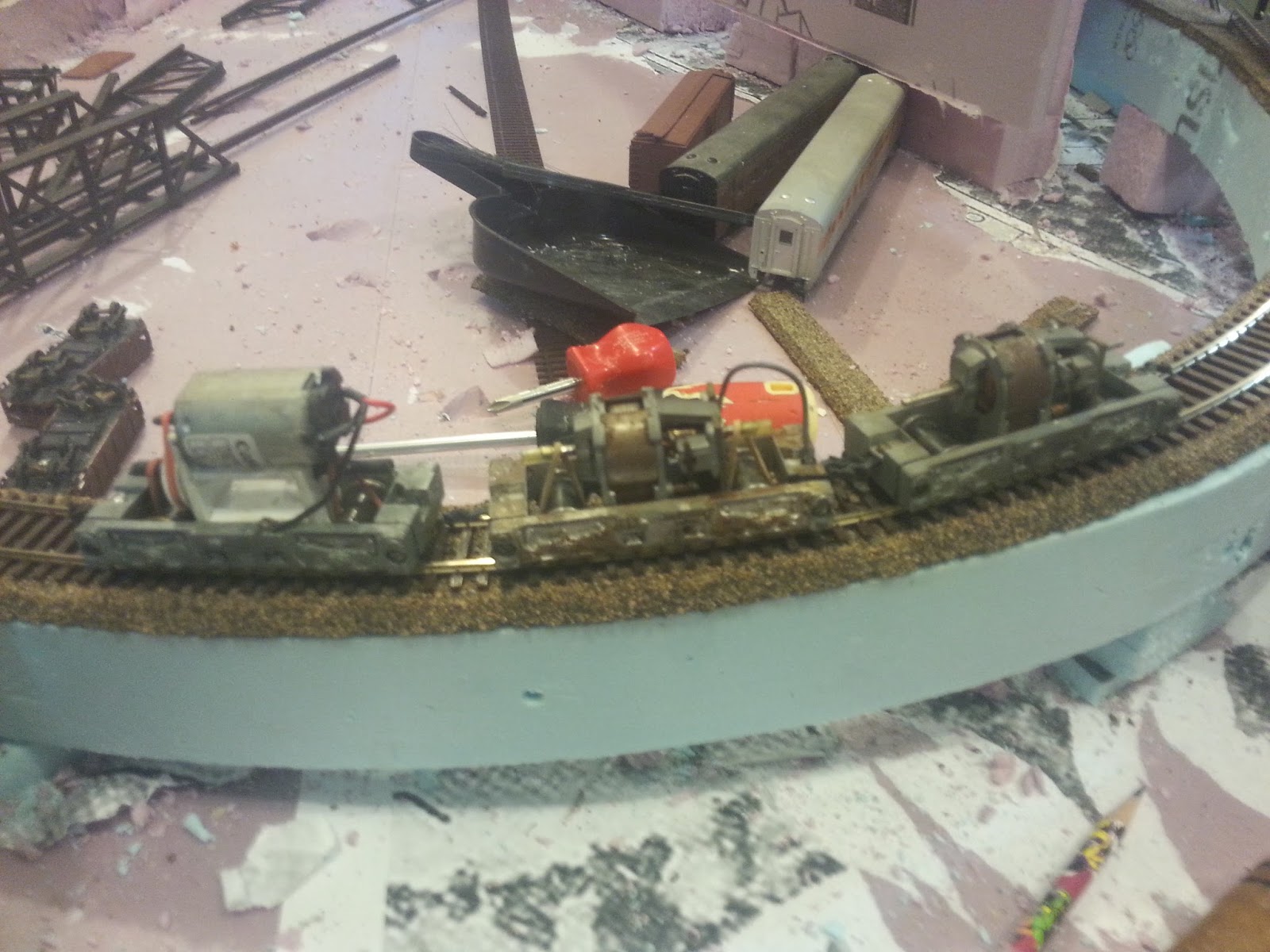
In 1959 Irv Athearn released a short industrial switcher patterned after a Porter product. While the little critters were perfect for very small layouts with tight curves, they had one major drawback. Switching industries is something that should be done at low speeds. The Athearn Hustler, however, really wasn't capable of low speeds. Case in point this pair of the tiny diesels. The Split River side of the layout has a rather straight section of track we call the "racetrack". A yard stick is purposely mounted on the fascia for timing the passage of  locomotives through this area. It took less than a second for the Hustler pair to cover the run. It was impossible to actually time them traversing the speed trap, they were traveling too quickly...

17,800 MPH?


I had to look at the video to get a better idea. I paused it when the Hustler's hit the one end of the yardstick...The clock reads 00:00:00 / 00:00:09. The clock hits 00:00:01 / 00:00:09 after the Hustler's pass the 36" mark. If I'm reading things right, 00:00:01 is one tenth of a second. Checking the Railroad Speed Calculator we find the locomotives are traveling at 3600 inches per second. That's just shy of 17800 mph in HO scale. I must be reading this wrong. If it's correct, the critters are traveling at a velocity that would put them in orbit if the Earth was HO scale.

On the bright side, switching chores would go very quickly, provided anything survives.

In other news...

For Christmas I received two Digitrax SDH166D sound decoders. Both of these have been allocated to the Q Company boxcabs. I connected one to a Travis drive Hustler to see what was what. I set it for the default diesel, a GP38. It growls just like it should and growls louder as the throttle increases. The bell sound is loud and clear. The horn sounds like a horn. It's also plenty loud...

Digitrax SDH166D Default Diesel Sound


Hold on a moment. It is much louder and clearer than the whistles on the steam locomotives. What's up with that?

I've been trying to find out if there's a way to make the whistles louder, but apparently nobody's complained so far. Fiddled around with volume settings etc. Tried a bunch of things. Then I happened across the solution. There are three settings for the whistle/horn on the CV #150. One, 00, is the the default. The second, 01, is a playable horn. The third is 128 plus 2 (why don't they just say 130) for playable horn with volume. I set my locomotives to 01, the playable horn.

In an effort to get more familiar with Digitrax decoders I downloaded the PDF of their manual, Mobile & Sound Decoder ManualSecond Edition  Buried in that rather lengthy tomb is a plethora of info, but nothing on my issue. Then, while reading through I came across a reference that implied that Digitrax controllers have a special pressure sensitive function button for horn playing. I'm using the Lenz/Atlas Compact/Commander. Ain't no pressure sensitive anything. The playable horn was useless. I reset CV 150 to 00, and what do you know, the whistle sounds fine. I can hear it from the other side of the layout. In this video I recorded the sound of two different locomotives. The first, 4-4-0 #5, has the decoder set for playable whistle. The second, 2-6-0 #4 is using the default whistle. You may not be able to hear the whistle on #5...

Digitrax SDH166D Decoder Default Steam Sound


I'll be playing around a bit more with this programming CV thingy.

Regards,
Frank Musick

Thursday, December 24, 2015

Draping the Facade

Scenery is beginning to take shape on the Split River side of the layout. Once again I'm using scrap styrofoam as a base for the shop towels. The bed of the river (and the creek) is actually the top of the styrofoam slab the layout is built on. I didn't take any particular care to create "realistic" landforms. I just piled the styrofoam scraps into what seemed reasonable and fit around the roadbed...

The facade around the layout was notched at the watercourses. These notches currently provide a good place to rest the hand throttles. Eventually  I intend to make "holsters" for the throttles, something that hangs from the back of the fascia.

I also put up the skirting that hides the legs and other junk under the layout. It's attached to the back of the facade with thumbtacks. Each side of the layout has a separate skirt so I can easily access the space underneath...
Shenaminy Creek Side

Split River Side

Quotidian Side

I made a "movie". Nothing spectacular, just bits of video taken as the trains move about the layout. I tried to capture the sounds of the steam engines. The noise in the background comes from #4, a 2-6-0 and #5, a 4-4-0 idling on the siding in Quotidian,"waiting" for an assignment. . Number 3, a 2-6-0 camelback, is out on the mainline with a short train. The video follows Q Company ore trains as they travel up and down between Mine #12 and the outside world. Six or seven cars is about the total length of train the two "oil electrics" can handle together...
Quotidian: The Andyrobertsite Story


Regards,
Frank Musick

Sunday, December 20, 2015

Photography, Short and Sweet

For a long time now I have wanted to take photos of my models. I have been using the shoot from the hip phone captures, or the images from my digital camera. What I wanted was a real honest to goodness photo like you see in the magazines. You know, the ones where everything in the frame is in focus. These photos are taken with an infinite depth of field. The problem is getting there.

I was able to make such photos using my 35 mm Pentax, but I used a pinhole diaphragm I made with a plastic disc. I cut the disc to fit behind my UV filter using a compass/dividers. This allowed me to create a circular form with a tiny hole in the exact center. It worked OK. It had one issue, however. You needed a LOT of light to take the photo.

Then a couple of years ago my son in law gave me his Nikon F100. He had purchased a new digital and the F100 is a film camera. I didn't mind at all. The only difference was the film. The camera had all the bells and whistles one could ever want. Autofocus, autoeverything. Trouble is, I had no clue how to use it. I studied the manual, but decided to just use the thing with the factory settings. Really could not learn how to use all those buttons, switches and levers. A whole lot to remember.

Some months ago, maybe two, I was going thru my old Model Railroader magazines. I came across an article written by John Allen in July of 1946. That changed everything. I don't know if you have ever seen any articles on photographing minatures, but they usually entail A, start off as a rocket scientist or B, modify the camera in some way. B seems to include tearing apart a perfectly good camera. I'm pretty sure that this would lead to a totally useless camera. No joy there. Mr Allen's article makes no mention of this. The article is about two pages long and relates how you can take photos with infinite depth of field. No modifications or degree in quantum physics required.

John describes how you use the camera settings, particularly the f stop, to increase the depth of field. He also created this chart of exposure times...
John Allen's Exposure Chart

So I grabbed the F100 and went out to the layout. I have two lenses for the camera, both automatic. One of them is a macro lens. This is sort of an all inclusive lense system that can zoom from f2.2 out to infinity. I chose this one first because it had the lowest f stop of the two. I set the camera for aperature priority (requires one button) and started taking pictures. This is the best I could get using f2.2 with the macro...
Macro Lens f2.2 Aperature Priority

It's pretty obvious this isn't what I was looking for. Everything in the foregound and the background is out of focus. I tried a few more times with the macro lens and always got the same results. For the last four frames I switched to the standard lens and set it a f3.2, again with aperature priority. Presto magico...
 Standard Lens f3.2 Aperature Priority

Aside from using too much light this is exactly what I was hoping for. To top things off, I didn't have to use John's chart. I let the F100 worry about the exposure time. The film I used was from Walgreens, ISO 200 (I think). The field of view is perfect...

Voila!

If there's one drawback, it's waiting for Walgreens to develop the film. I don't think I want my own darkroom.

Regards,
Frank Musick

Friday, December 18, 2015

Shop Towel Scenery

Terrain is starting to appear, at least it is on the town side of the backdrop. On the previous layout I had used a cardboard lattice covered in paper towels. The towels were soaked in thinned drywall mud. This time around I had a bunch of styrofoam left over from the earlier project. The styrofoam will form the general contour and the towels will be draped over that...
Styrofoam Terrain, Shenaminy Creek

Quotidian Looking West
I have found that the quality of the paper towels I use makes a big difference. The cheap two ply towels come apart in the drywall mix. More expensive towels tend to come with a quilted pattern of some kind. This looks kind of strange when used as a scenery base. I found some paper shop towels while buying a car battery. Perfect!
East Quotidian

A few more realignments were performed. The first eliminated the handbuilt turnout at the "west" end of Quotidian. The track arrangement will be changed a bit and an entirely new set of turnouts will be built. The other change adjusted the grade at The Hump. Locomotives no longer have to struggle to reach the mine. Double heading is still required on long trains (7 cars or so), but there is no stalling.
De Humped
Which brings us to the locomotives themselves. Because of the space required by my version of the Travis drive, the original Hustler shell is too low. A smaller pulley would allow this, but I wasn't concerned. The locomotive the Hustler represents is too "new" for my purposes. The branchline engines are supposed to be first generation boxcabs...
1st Generation Boxcab, 65 Ton Mack

I used sheet styrene to create a freelance model of something that would fit the Hustler frame. The first version looks a little too European to me, like something you might see on the Isle of Sodor...
Boxcab 1st Design

The second design looks a bit more American. Although it still needs a bit of work and lots of rivets, the basic lines are there The radiator is made from styrene blocks and rods....
Boxcab 2nd Design

I had trrouble getting the window openings square. The sanding "sticks" I was using are those flexible foam core kind. I switched to Revlon emory boards. I cut them into scale widths of 1', 1.5' and such. They do a much better job...
Sanding Boards
Regards,
Frank Musick

Wednesday, December 9, 2015

The Hump

Bridges, bridges bridges. They're fun to build, especially when you're not following any prototype whatsoever. They do, however, consume mass quantities of stripwood. The guys at the local Hobby Town now know be my first name.

I won't go into detail on how I built them. Suffice to say you create a template and construct the trusses, bents, whatever on top of it. I've been using superglue gel to hold things together; much faster than wood glue. I've also started using Testors "burnt umber" paint instead of stain, painting after the bridges are assembled. In the case of the Shenaminy Creek trestle it took hours to paint. All those nooks and crannies. I installed it and you know I just had to stage some photos...
Twin Hustlers and Ore Train, Gas Electric Cross Shenaminy Creek


The Bridges at Quotidian

There's a second Travis Hustler now. This one took a bit of tweaking. I purposely built it lower, hoping to get it low enough to fit the actual Hustler shell. The size of the pulley cancels that idea. I ended up adding a spacer to make it taller. After I got it running I took some video...
Travis Drive Hustlers

I need boxcab shells for the Hustlers, something that resembles the "oil electic" diesels produced in the 1930's. I could kitbash a few of the Athearn shells. I could also try again to find a Cary shell, but I'm trying to build them from scratch. I've taken several shots at it, but I'm not satisfied with the results so far. Window openings are unsquare. parts don't fit nicely, just general poor appearance. Practice, practice practice...
"Travis" Boxcab Shell


Starting on some of the scenery. Using scraps of foam I'm slowly building the terrain. A big part of the process will be the town itself. I'm building it on a workbench. The entire town will be on a piece of 2" foam I can drop into place.  I tried laying the town out on paper but couldn't get the "feel" of it. Ended up but creating a paper template of the area available and laying it out with real buildings, mock-ups and track. The viaduct is virtually finished and the overall appearance of Quotidian has changed a bit...
Engine Terminal and ACME Manufacturing

"Skyline" of Quotidian

Trackside

I completed the branch somewhat. Had to realign one curve that was so tight the Hustlers derailed. I also had to smooth out the grade between Shenaminy Creek and the Split River. This area is now called "the hump"...
Realigned Curve Before Viaduct
Shims to Ease Grade at "The Hump"


Trackage is complete enough to actually run a train. The train is short, only four cars and a caboose. Good thing too. In spite of the reduced grade and an additional 2 ounces added to the weight of each locomotive it still requires both boxcabs to conquer the hump...
First Q Co. Train

Regards,
Frank Musick

Tuesday, December 1, 2015

A Mystery, Masonary and a Herd of Hustlers

Found this image in an old Railroad Magazine dated May, 1949. Upon first sight it looks like Rube Goldberg's version of a self-propelled railcar. Very "steampunk" to be sure. I suspect it could be a product of a fertile imagination, but knowing the whimsy of railroad design before the Civil War it could well be a rendering of a real piece of equipment...
The "Colorado"


Many of railroadings pioneers seem to have let their imaginations run wild while designing equipment. The single set of tall drivers shown on the "Colorado" also appeared on British "Cramptons" and the Camden & Amboy's "John Stevens". One of several 6-2-0 locomotives designed by Isaac Dripps and built between 1849 and 1853. If I recall correctly, those drivers were nearly 8 to 9 feet in diameter. They tended to slip getting underway but could zoom along at a pretty good clip. The solid panels between the driver spokes are not ornamental; the big wheels worked like giant fans at speed, spraying debris and dust along the right of way. Closing off the wheels eliminated this curious behavior. After several year of service the engines were rebuilt as 4-4-0's...
Camden & Amboy "John Stevens"

Like I said, it's not unlikely that something like the "Colorado" could have been real. Since the tin-type may be the only evidence of it's existence we'll never know.

Meanwhile back in the present...

I started "detailing" the Quotidian viaduct. I took that embossed stone paper I purchased a while back and traced the viaduct on the back...
Tracing The Viaduct

Then I took a triangle, lined it up square with the paper and drew over the traced lines so the they were 90 degrees from horizontal...
Squaring the Tracing
Using a #11 hobby blade and the triangle, I cut along the center line of each arch. I also made a perpendicular cut 17 scale feet from the bottom of the paper. The paper within the arch got cuts every 45 degrees...
Square Cuts

The vertical cuts were on the arch centerline only. This let me fold the paper in at each arch for the lining of the masonary...
Finished Cuts

I spread some glue on the viaduct side and smoothed the paper using a plastic painters tool like a squeegee...
Tacky Glue
Smoothing Paper and Painters Tool


Then I folded the paper inside the arches to simulate the stone lining. The curved part of the arch was also folded in. The 45 degree cuts allow the paper to conform to the curve...
Lining Arches

Once I got all the paper on the sides I added more paper on the verticle sides of the arch and lined the arch itself. Unfortunately, I forgot to take pictures of those steps. The almost finished product looks like this...
Stone Viaduct

Still needs the keystone and such at the tops of the arches. I ran out of stone paper so the other section of viaduct may be done in one of the other papers. Not sure which...
Embossed Papers

Right now I'm fooling around with a trestle that carries the second loop of the branch over Shenaminy Creek...
Shenaminy Creek Trestle

A few more EBay purchases came in yesterday, including two Hustler mechanisms. One will replace the twins unit I "borrowed". The other will receive a Travis drive and boxcab shell. Several ore cars full of andyrobertssite or coal can get pretty heavy. It will often be necessary to double head the boxcabs on the branch.
A Herd of Hustlers


Regards,
Frank Musick

Saturday, November 28, 2015

Shenaminy Creek and the Split River

The mainline and the branch cross over two watercourses. In Quotidian the Shenaminy Creek passes through a culvert and under three bridges The first bridge is a low wood trestle carrying the branch tracks. The second bridge is a plate girder bridge supporting the mainline. The third bridge is a tall wooden trestle carrying the branch tracks over the creek a second time. The two lower bridges are followed by tunnels while the high trestle leads to deep cut through the summit of the mountain...
Girder Plate Bridge Over Shenaminy Creek


The mainline plate girder is the only bridge installed so far. The other two, the trestles, are under construction at the workbench.

I decided that all the bridges on the branch should be constructed of wood. Over the Split River I decided to uses this freelanced design of a Howe truss...
Howe Truss

Building the Howe caused me to modify the other wooden bridges on the layout. The trusses built before the Howe were faked up using only a single thickness of wood...
Howe Versus Earlier Truss

The Howe, though still not "correct" looks a lot more substantial than the trusses created previously. I made a point to go back and make all the earlier bridges look better. I did this by adding more lumber to the top and bottom and stringing piano wire that mimicked the new truss...
Viaduct Modified Truss


I stained the bridges after assembly with "provincial" furniture stain. The stain, however, could not cover any glue spots. I had to mix a "creosote" shade of brown and black flat enamel to paint those areas. I also tried pre-staining, but found that CA glue wasn't sticking properly. Painting after assembly seems the best approach.

Anyway...I assembled the Split River bridges and installed them. The Warren carries the mainline. The branch crosses over the river on the other two...
Split River Bridges

It looks like this may turn out to be a great spot for photo's. The bluffs on either side of the river are very steep, almost vertical in the higher elevations. The river itself is still a wild mountain stream of falls and rapids...
Split River, High Angle

Now it's time to get back to Quotidian. The viaduct needs painting and stonework, the town needs to be layed out.

Regards,
Frank Musick


Innovations

Laying out the viaduct it became obvious that the branch right of way needed realignment. While this could have been avoided with "proper planning" I don't work that way. Despite all the fuss about it from some modelers I don't mind doing it twice (or more). If the end result is what I can live with it was worth the extra effort.

Fortunately, the styrofoam spline I use for road bed is very forgiving. You can realign it very easily. It gives to a certain extent. A curve can be formed to a tighter or wider radius just by screwing the spline in the desired position. I chose not to do that, however, and created a new section of spline instead. I added a few "innovations" to the new construction.

The roadbed can be cut with a razor, exacto knife etc, but I chose a Zona saw, what I call the "short sword". It's a keyhole saw of sorts, with a very pointy end that's great for pushing through the foam when need be.

First I cut out the section I didn't want anymore. I lifted the whole thing off the layout and set it aside...
Removed Spline

You can see that, once the glue dries, it's easy to remove large sections. The spline also maintains its shape, very convenient in case you want to use it somewhere else. I'm not reusing this piece. Instead I'm laying new spline.

The first step is to cut more spline strips. I use my trusty straight-edge, originally meant to cut drywall. It came in two four foot sections. I modified mine so it is permenently eight feet log. It has a stop along its length made of channel set to cut 2" strips. The cutting side is square to the foam...
Straight-edge

I simply lay it over the 4' x 8' by 1/2" foam and run a razor blade along it. In the past this has worked, but the cut was not always square, so the spline top wasn't level width wise. Most of the issue was caused by me, cutting too fast to be accurate. This time around I went slower, cutting in several passes and pressing the utility blade hard against the straight-edge to ensure the cut is square...
Slow Versus Fast Cut

Once the strips are cut I start building the spline itself. First I notch the existing spline so it overlaps the center strip...
Notched Spline

The notch creates a stronger joint and centers the new section. I coat the joint with glue and drive in some drywall screws to act as clamps. Most of the time these screws are left in place to help hold the spline together...
Splicing Splines

In the past I've created the entire spline at benchwork level and then elevated it. This works well, but this go around I decided that all I really need to construct is the center strip. I elevated the strip starting at the known height of the viaduct at Quotidian. I used other existing supports as height guides. Rather than using stacks of leftover foam I created notched pylons. The pylons support the strip, the notches keep it centered....
Old Supports, New Pylons

I made the pylons all the same size, necessitating a second piece to raise the spline to the proper height. All the new supports are two piece, rather the hodge-podge stacks of various thickness foam. Thinking back on it the pylons should be fashioned from one piece of foam cut to the correct height.

Once the center strip and pylons were located and glued in place I started on the outer strips. With all the earlier splines all the strips were continuous. In this new construction the outer strips only run between pylons. Once again I use a combination of glue and screw to hold the strips in place...
New Spline

In areas where I thought I might need to change the curve radius I also installed "outriggers". This is just another spline strip running on either side of the supports.

There are several places on the branch that required special handling. The first is where the branch crosses over the mainline inside the mountain. There is not enough room to fit a standard pylon. I had to create a "bridge" to support the roadbed. I used a section of plywood mounted to the lower supports...
Roadbed "Bridge"

The other location is where the branch and the mainline pass under the mine. This is another mountain with tunnels for the mainline and the branch. I placed my NMRA clearance guage to see what needed to be removed....
Clearance In Mine Area

Rather than mess about with modifying the existing roadbed I simply removed and replaced it with a large section of plywood supported on substantial foam blocks...
Plywood Mine Support

The one place I found the most troublesome was the corner at the far end of the viaduct. The track gets VERY close to the layout edge. I filled in the entire corner so I could create a tight curve with a nice transition...
Filled Corner
With the spline complete I have to make places to add all the bridges I'm building. This will require some more cutting and trimming.

Regards
Frank Musick