Saturday, September 28, 2013

So On and So Forth

Still looking into kitbashing an H class 2-8-0. Found out that Kato makes a model of a Japanese 9600 class Consolidation. For me it's wiser to buy the drive from the parts department rather than cannabalize a perfectly good locomotive. I checked the Kato Japan parts site, but no 9600 drives are available. Kato Japan seems to stock parts on a random basis so I'll keep looking...
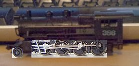
Kato/Trix Bash

The Centipede project is still on hold. No response from the software publisher. I've thought of buying the newer version of the software but I'm not sure that would solve other technical difficulties I'm having with the model.

Trackwork has started on the layout. Yesterday I laid about fifteen feet of track. Took a while. Keep in mind that this is 15 x 4 or 60 feet of code 55 so the actual progress went better than it sounds. Heading west from Spruce Creek we start with Forge Curve...
Forge Curve From Spruce Creek


In the real world there is quite a bit of real estate between Spruce Creek and East Altoona, including Tyrone and the junction of several branches...
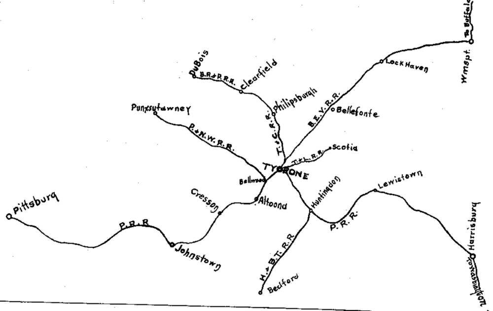
Tyrone Today
Maybe someday when I own a football stadium I can include more at this eastern end.

On the layout Forge is directly east of Homer, so close that the elevation of Track 2 starts just west of the Spruce Creek tunnels. The separation of the eastbound and westbound mains continues though the curve into Homer...
Forge Curve and the "Ramp" to Homer
 The mains converge for about a foot and then split as the passenger tracks pass under Track 4 while Track 1 continues west on its own...
Homer Looking East

On the prototype the PRR literally created a huge fill and constructed the westbound arrival yard. Homer was at the west end of this yard and the top of the "hump" for the westbound classification yard. There is no way to replicate this arrangement on the Allegheny Eastern (short of changing to Z or T scale). I opted to create the appearance of Homer instead because A - It avoids a complex set of crossovers that would be required other wise and B - I like the way it looks...

Staged  Action at the Homer "fly over"

In the image above an L1 hauls a westbound consist of automobile empties over the "flyover" Atrain hauled by an EF4 (A-B-B-A set of EF15's) heads east on Track 1 as two passenger trains pass on Tracks 2 and 3. It's a staged picture of course, but I couldn't help creating a preview of the finished layout. The trains aren't actually trains, just locomotives and some cars as can be seen in this image of the west side of Homer.

Homer as Seen From the West Side

I got as far as the yard approaches at East Altoona where the tracks leave the spline roadbed and run on the slab of 2" thick styrofoam. 

Tracks 2 and 3 Looking Back From East Altoona
Tracks 1 and 4 Looking East

Once again taking photos of progress on a a project helps you see flaws your eyes (and brain) tend to gloss over. Although I'm fairly happy with the linear look of the mains, I can see there are vertical dips I need to correct. They may just be distortions in the picture, but at least I know where to use a straight edge to check things out.

Next I take the rails through Juniata. The challenge will be getting the tracks perfectly straight and parallel for the next fifteen feet. I find the curves can be eyeballed but straight sections are a great deal harder.

Regards,
Frank Musick
Chief Cook and Bottle Washer
Allegheny Eastern Railroad


Thursday, September 26, 2013

Back in the Saddle

I was able to get the roadbed for the passenger mains straight after a bit of adjustment. It involved running to the end of the layout and checking how things were lining up. Only took about sixteen tries. It was worth it though. There are now four reasonably parallel "tracks" running through Juniata...

Juniata

Now If Only I can Get the Track This Straight
Once I got that roadbed straightened out the strip went down pretty quick. In a short while I had laid strips all the way to Brickyard, the first 180 degree curve...
Looking Back to Juniata From Brickyard

Climbing The Hill I laid the two outside strips, lining them flush with the outside of the roadbed. The inner strips were laid by eyeballing the spacing...
Heading Towards Wikes Curve from Brickyard


Within a few hours I managed to lay ballast strip to the future location of KN tower. We're about 50 track feet from Spruce Creek, about a third of the way around the layout...
Wikes Curve Toward Horseshoe

KN Tower
The time I spent includes cutting a fresh batch of ballast strips. I used those up and had to stop for the day.

The next day I cut a whole new batch of cork. A few hours later I had ballast strip laid for all four tracks all the way to the summit...


Horseshoe
Bennington


Gallitzin
Track work begins at Forge Curve just west of Spruce Creek. Should start tomorrow.

Regards,
Frank Musick
Chief Cook and Bottle Washer
Allegheny Eastern Railway


Wednesday, September 25, 2013

Player Sleeps With The Fishes

Excuse me for falling back on my video game days, but that's the way things seem to be going. The 3D printing project came to a complete stop when the software I use went south. I reinstalled, but I'm having problems with the enabling the features I need. Can't export stereolithograpy files anymore.

On the positive side I now have enough Bachmann DD40's to build the drives for two centipedes. In Pennsy speak this is the equivalent of one Pennsy BP2 (BP60 in normal PRR classification). It seems a bit wasteful to toss 90% of the locomotive away but I only need the powered trucks. The other parts get sold on E-Bay, a commercial endeavor that may or may not be considered successful so far...
A Bevy of Bachmanns

So the project isn't dead, just in limbo.

For all of those who have been waiting for news on the actual layout I got off my keaster and spent some time in the garage. I think one reason I've been holding back is this whole soldering of rail joints. Trackwork on the helix went extremely slow because A- I wanted to make sure it was right B- I soldered all the rail joints. Soldering, as simple as it is, is like going to the dentist. Something absolutely necessary but something to be avoided. Frankly, I would rather have a root canal.

But then I found something that appeals to me, something that may replace solder on Allegheny Eastern rail joints. There is a product called Wire Glue. It's a concoction of carbon and adhesive that conducts electricity. I started using it on my rail joints. Does it work? I'll let you know. Only cost $5 to find out. I'm thinking that if it does work it may also be just the thing for locomotive drivers. If paint can be used to increase traction, conductive paint might be even better. Strange idea? Probably, but then you're talking to a guy who makes roadbed out of strips of Styrofoam.

Which reminds me...Remember all that discussion about reinforcing that same Styrofoam roadbed to carry significant loads? I tried a couple of different approaches that seemed to work well. Then one day I was doing something totally unrelated to trains and it struck me...I should use strips of 1/4" plywood! I'm not sure what load that would carry but I bet it would be noteworthy.


Ok so what have I done with the actual layout. I started laying down ballast strip west from Spruce Creek...
East of Spruce Creek
I cut my own cork strips (WAY cheaper than manufactured ballast strip) in 8 or 9 foot lengths. I apply a generous helping of tacky glue with a brush and then lay down a cork strip. Simple enough. The fact that the roadbed is exactly the right width makes lining up the strips a snap. I just make sure the cork is flush with the sides of the Styrofoam and it's where it ought to be. There are some places this doesn't work, but they are transitions and not very long...
Ballast Strip Transition
These "transitions" are essentially places where the ballast strip moves so that it's flush with the opposite side of the roadbed. This maintains the proper spacing between the tracks

I had spoken before about the flexibility of the Styrofoam spline. I had some occasion to prove that approaching and leaving Juniata yards...
Passenger Mains Misaligned, East Altoona
You can see in the photo above that the passenger mains missed the track plan on the slab by quite a bit. Aside from providing proof positive that proper planning is a good idea, it gives me an opportunity to exploit the OOPS factor built into the spline. All I had to do to correct this was loosen the screws holding the spline in place and realign it. I ran into the same problem with the freight mains at the west end of the yards...
Freight Mains Misaligned, West End Juniata Yards
Once again all I had to do was loosen the mounting screws and bend the spline...
Corrected Alignment,  West End Juniata Yards
One other area that presented a challenge was the yard bypass for the passenger tracks...
Crooked Roadbed

This section was hard to line up properly because it's inconvenient location. It's at the center of a 3 foot wide portion of benchwork. There's no real way to eyeball the alignment except from either end of the yard area about 7 1/2 feet from the middle of this area. Unfortunately my arms are too short. I'm still working on this, but it's the same process to correct. Loosen the screws, line it up and fasten it down again. 
Bypass Tunnel at Homer
One other thing I had to do came to my attention while laying ballast strip. It isn't really feasible to use a hole saw to create the tunnel bore. I have to do in what was probably similar to the way the PRR did it. The gap will be bridged and the tunnel bore built and filled.

The ballast strip is about a third of the way around. The track will be laid and nailed into place over the entire layout and after the track has settled a bit the joints will be glued and/or soldered. I was going to glue the track in place, but have gone back to the idea of letting the ballast hold it down. The glue that secures the ballast will also fasten the track in place. When the glue has set and dried the nails will be removed.

Regards,
Frank Musick
Chief Cook and Bottle Washer
Allegheny Eastern Railroad


Thursday, September 19, 2013

Roll your Own

If Kato or Athearn won't produce the models needed for the Allegheny Eastern I'll take a shot at creating my own. N scale PRR modelers have been doing it for a while now. It's more fun. It's also cheaper if you use the right priced parts. Locomotives like the BP20 passenger "shark", the H class 2-8-0, or the giant BP60 have to be cobbled together i.e. "kitbashed".

Which brings us back to the current obsession, the BP60 "centipede" I'm creating for 3D printing...

PRR Class BP2 (BP60)

I started this crazy project and now I am determined to see it through come hell or high water. Shapeways wants it hollow. Well alright then, it's hollow...
Inside The BP60 "Centipede"
I'm not really complaining, though I do wish I had stayed in the garage and laid some track. It was a challenge to hollow this beast out. Along the way I also developed a whole host of techniques for making these "CAD" drawings easier and more accurate. Little hard to explain, but the picture may give you an idea of the results.

Right now I'm waiting on 3D Canvas to munch it's way through the translated file. I'm trying to see if I can "solidify" the model using the utilities in 3DC. It's taking forever, probably owing to the complexity of this beast. With almost 61000 Vertices and about 92000 polygons it's the most detailed model I've ever made. Train Simulator doesn't really tolerate complex objects. As a result I had to learn how to do things in the simplest way possible. This is exactly the opposite.

PRR Class BH50
The Pennsy centipedes were configured quite differently than their cousins. The most obvious difference is the lack of "portholes". The only porthole on a BP60 is in the rear door. The BP60's also have the louvered roof panels that other centipedes lack. I tried to make the model as Pennsyesque as I could. I used photos of the real thing as well as models by BLI, Lionel and anybody else who's attempted to replicate these monsters. I have detailed drawings, but not of the Pennsylvania version. I do have the PRR drawings, but they are more of a schematic that an actual plan...
PRR Drawing E437703-R-RC
It did give me locations for items like the water and fuel fillers as well as the sand hatches...
Fuel Filler (Red) and Sand Hatch
Water Fillers (Dark Blue)

I show louvers, but they don't exist on the BP60. They were on the detailed plans (Seaboard #4500, the first DR-12-8-30). I'll be deleting them before the file goes back to Shapeways. While these small details are nice, it's very likely they will disappear on the finished model. The CAD version shown here is technically full size and measures about 80 feet long. It will be printed in N scale, 160 times smaller.

The biggest problem in preparing the model is making it what Shapeways calls "watertight". Basically this means there can't be any "holes" in the model mesh. The "holes" can be filled using software that allows you to edit the mesh. Unfortunately, using the "fill holes" function tends to fill in things like window openings and such. It took a few days to figure out a way to solve this and the solution is tedious to say the least. I fill all the holes and then reopen the windows, intakes and the like. Great fun! Lucky for me that the software highlights what I need to remove. Selecting the offending blockage is easy. point click and TADA!...wait while the program completes the process. It takes quite a while for each deletion to complete and there are a lot of them...
Highlighted "Blockage" in an Intake Opening

In other news, I've been buying up mechanical parts for the model. I was able to snag two more Bachmann DD40 models on E-Bay. I got two of them for less than $30. I now have enough parts to build two centipedes with two power trucks each. The only misgiving I have is the Bachmann motors are three pole without skewed armatures. These older motors tend to "cog" as they rotate at slow speeds. I have some inexpensive Life-Like motors with skewed armatures that will run a lot nicer. There's a problem, however, in "swapping" them for the Bachmann's. While the motors themselves are the same size, the Life-Like motors have external bearings that may or may not cause problems with the gear alignment...
Motor Swap
Hopefully you can see the thin blue lines in the image above. These mark the outer ends of the bearings on the Life-Like motor. You can see that this would push the worm gears way out from the drive gears. While there is some degree of adjustment, it may not be enough.

In other news, I've been working on building up the steam roster on the Allegheny Eastern. I recently purchased a bunch of Minitrix steamers off E-Bay, including a couple of 0-6-0 switch engines. These models are supposed to resemble the Pennsylvania's B class. While they may, the real reason I purchased them is because they also look a lot like the PRR's Consolidation (2-8-0) or H class. Most of the later H's were short and stocky. The only side view I could find of one is of a model H10 but it gives you a good idea of the appearance of these little beasts...

H10 Model

I've read that many modelers use the Trix shell to model the H. The cab is combined with the boiler of a Trix K4s to create a better looking replica. I myself have no qualms about using the Trix switcher shell just as it is. Aside from the dome arrangement and a slender boiler the short length looks good on the 2-8-0 running gear. Thanks to the wonders of Paint Shop Pro I can show you what I mean...
N Scale H Class "Kitbash"

With the proper paint and smaller lettering it will make a passable H class. Both of the switcher shells I own are cast metal, not the plastic used in later versions. It's a Zamac alloy or something and would be murder to try to cut, even with a power tool. Best left alone. The running gear is actually from a Mikado (2-8-2) I had laying around. The motor is absolutely too long for the swap (I cropped it out in the image). I may end up finding another chassis for the thing. Since I plan to build two of them I should matching mechanisms. The old Bachmann Connie, modeled after a Reading engine, is supposed to be a good candidate.

That's all the madness for this week,

Regards
Frank Musick
Chief Cook and Bottle Washer
Allegheny Eastern Railroad


Monday, September 9, 2013

The Joy of Printing

As far as I can tell, about 60-70 people view this blog on a regular basis (or one guy with a very short attention span). I'm honored that those 70 (or one) find this babbling interesting enough to read. Then again, it may be like that Miley Cyrus video. Like a train wreck, you keep watching it over and over.

Anyway, I get the general feeling my fellow human beings are softly saying "Will you get the damn track down already!" every time they visit. I really am working at it. There's not enough to show yet. Then too, there are no blunders in the process to share. So the work goes on.

But then I received an e-mail from Shapeways on the centipede "blank" I submitted. I quote...
"Here is why we cannot print your model:
Model should be hollow, too."
Shapeways "Diagnosis"


Had to laugh. I had sent a hollow model to the "other guys" and they canned it. I had made the walls too thin. That's why I sent a solid object. The "other guys" were OK with the solid, but too expensive ($114 US I think). That's why I went with Shapeways. You'll see the image above indicates the "Deatils will be covered over in glaze". This is because I was being clever and thought I could save some money by having the shape produced in black ceramic. Price difference is on the upside of $20. There was a sandstone option that probably would have worked but I should have taken the hit and gone for plastic. There are just some things you have to spend money on.

The upshot of all this is that now on another tangent. I'm obsessed with the centipede model. As soon as I got the e-mail I started reworking the shape. I added (subtracted?) material from the inside. This made me realize I could now add window openings. While I was doing that I realized what has always bothered me about the appearance of the nose. Doesn't look "babyfaced" to me. Then I saw that I had rounded the top of the nose too much so I changed that. This meant I had to change the rest of the nose to suit. Correcting the nose led to changing the cowling and windshield which in turn affected the forward sides. Then I added the side window opening in the cab, etc and so forth. I went whole hog and created the actual model I want to print...
Centipede in Train Sim Modeler

As always, I'm doinng this the hard way. As I said before, the original digital shape was created for Microsoft Train Simulator. I use a program called Train Sim Modeler. It was originally created for shapes in Flight Simulator and adapted to MSTS. It's interface is pretty simple, but much like a CAD program. I should use an actual 3D development program like 3D Canvas or Blender, but the learning curve is steep. I do use 3D Canvas, but only for translating the TSM files to STL (stereolithography) format for the 3D printer. 
Centipede in #D Canvas
I then import the file into a program called Meshlab. Meshlab lets me analyze the model and "fix" any problems. Simple, right?
Centipede in Meshlab

So...I save the "massaged" file from Meshlab (still STL format) and send this file to Shapeways. The trouble is the new detailed file is stuck at the Meshlab phase. The software keeps detecting what are called "non-manifold" edges. While I don't completely understand the whole "non-manifold" issue I do know it means the model cannot be printed. The original solid shape had very few errors and was easily repaired. This more detailed version is chock full of the little buggers. The program repots almost 7000, which may give you an idea of how complex these shapes can get....
Non-Manifold Edges

Anyway, I found that some of the errors were from duplicate surfaces, two identical parts in the same place. It happens. Sometimes it's hard to keep track of changes and you duplicate things. What I had to do was take the entire model apart (it has what might be called sub-assemblies). Then I started testing each subassembly for errors...
Sub-assembly, No Errors

This part is the first one I reworked when I saw the disastrous fail. As you can see, there are no errors. I found that the parts I expected to fail, the curved parts of cab, for instance, had few if any problems. If they did they were easily repairable. Meshlab says there are only 10 non-manifold edges after the rework, most of them in the cab...
Small Errors in Cab

The tiny non-manifold edges in the cab are repaired by deleting the related polygon faces and then filling the holes. The easiest place to do this is in the Meshlab sodtware. It's designed with utilities to make corrections like these...
Corrected Cab

You'll notice the program also can display information on the size of the object. Crteating an object in TSM is not an exact science. It's not like a program such as AutoCAD where you can feed in exact measurements. In TSM you build the object against a scaled backdrop, almost like you're tracing the shape. There is a dimension function, but it only allows you to check a measurement, not create one...

"Tracing" a Shape in TSM
Still, you can get reasonably close. You may have noticed Meshlab indicates a length of 79.91 units. In this case that's feet. My drawings of the centipede (PRR E437703-R-RC and a Model Railroader plan) drawn way back when there were centipedes) shows a coupled length of 91.5 feet. TSM says the model is 93 feet long. That's 0.10625" in the finished product. I'll take it. I'll let someone else worry about the discrepancy. It also shows 10' for the height. The actual height above rail with trucks and wheels is 15', about an inch lower that the real Baldwin.

Still a lot of rework and error checking before the files go back to Shapeways. I'll let you know what happens

Regards,
Frank Musick
Chief Cook and Bottle Washer
Allegheny Eastern Railroad


.