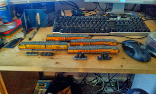
On the positive side I now have enough Bachmann DD40's to build the drives for two centipedes. In Pennsy speak this is the equivalent of one Pennsy BP2 (BP60 in normal PRR classification). It seems a bit wasteful to toss 90% of the locomotive away but I only need the powered trucks. The other parts get sold on E-Bay, a commercial endeavor that may or may not be considered successful so far...
 |
| A Bevy of Bachmanns |
So the project isn't dead, just in limbo.
For all of those who have been waiting for news on the actual layout I got off my keaster and spent some time in the garage. I think one reason I've been holding back is this whole soldering of rail joints. Trackwork on the helix went extremely slow because A- I wanted to make sure it was right B- I soldered all the rail joints. Soldering, as simple as it is, is like going to the dentist. Something absolutely necessary but something to be avoided. Frankly, I would rather have a root canal.
But then I found something that appeals to me, something that may replace solder on Allegheny Eastern rail joints. There is a product called Wire Glue. It's a concoction of carbon and adhesive that conducts electricity. I started using it on my rail joints. Does it work? I'll let you know. Only cost $5 to find out. I'm thinking that if it does work it may also be just the thing for locomotive drivers. If paint can be used to increase traction, conductive paint might be even better. Strange idea? Probably, but then you're talking to a guy who makes roadbed out of strips of Styrofoam.
Which reminds me...Remember all that discussion about reinforcing that same Styrofoam roadbed to carry significant loads? I tried a couple of different approaches that seemed to work well. Then one day I was doing something totally unrelated to trains and it struck me...I should use strips of 1/4" plywood! I'm not sure what load that would carry but I bet it would be noteworthy.
 |
| East of Spruce Creek |
 |
| Ballast Strip Transition |
I had spoken before about the flexibility of the Styrofoam spline. I had some occasion to prove that approaching and leaving Juniata yards...
 |
| Passenger Mains Misaligned, East Altoona |
 |
| Freight Mains Misaligned, West End Juniata Yards |
 |
| Corrected Alignment, West End Juniata Yards |
 |
| Crooked Roadbed |
This section was hard to line up properly because it's inconvenient location. It's at the center of a 3 foot wide portion of benchwork. There's no real way to eyeball the alignment except from either end of the yard area about 7 1/2 feet from the middle of this area. Unfortunately my arms are too short. I'm still working on this, but it's the same process to correct. Loosen the screws, line it up and fasten it down again.
 |
| Bypass Tunnel at Homer |
The ballast strip is about a third of the way around. The track will be laid and nailed into place over the entire layout and after the track has settled a bit the joints will be glued and/or soldered. I was going to glue the track in place, but have gone back to the idea of letting the ballast hold it down. The glue that secures the ballast will also fasten the track in place. When the glue has set and dried the nails will be removed.
Regards,
Frank Musick
Chief Cook and Bottle Washer
 |
| Allegheny Eastern Railroad |

No comments:
Post a Comment