Tuesday, November 19, 2013

Buck Rogers & The Allegheny Eastern

I recently met a mad scientist who has perfected a way to shrink objects to what ever size one desires. I helped him test it and we succeeded in shrinking a 1940 Ford Tudor sedan to pocket size. The only drawback was the mass. The good doctor hasn't overcome that problem. The car will fit in your pocket, but because it still weighs two tons you need a crane to lift it...
Ominous, Isn't It.
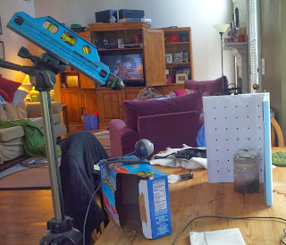
No, I haven't actually found a way to reduce a 1940 Ford to a toy. Would that I could. The deathray gadget shown above is a laser level. Normally used to produce a level line for all kinds of construction it's been adapted here to scan objects. I use the level to scan the Ford model and a digital camera collects the image...
Laser Scanner
The results are processed by a software called "David". The software is free, to a certain extent. It's a low resolution trial version that allows scanning any object into three dimensional data. The data can be imported into other programs that can manipulate the information and create digital copies. It can also be exported to 3D printers and reproduced as real objects.

The fact that the data can be manipulated means that it can be stretched in any direction or enlarged or reduced. You can for instance, scan a real 1940 Ford Tudor sedan and re-scale it to any size desired (no joke). Using a 3D printer you can re-size it to produce a 1/25th scale replica, or for that matter, reduce it to 1/160th scale.

I first stumbled across David when I was creating digital models for train simulators. Building realistic digital models takes just as long or longer than real models. Some of the shapes we take for granted, such as 1940 Fords, are very hard to re-create. Scanning a ready made Ford would be much easier. I had this idea that I could shorten the process by scanning objects into my 3D modeling software.

While some models, like my Baldwin passenger sharks and centipedes, could be reproduced through this process, I still have to build the first model to have something to scan. There are however a jillion other objects the layout could use that are readily available, but not in 1:160 scale. With David, I might be able to reproduce these items. It's similar in some ways to using Hydrospan for shrinking castings, but with a lot less mess.

The software essentially creates a cluster of data points, called a point cloud, representing the scanned object. The spatial data we used in the train simulators uses the same technology...
Geo-spatial Point Cloud
This point "cloud", as it's called, is the basis for a three dimensional mesh. The mesh can be used for a number of purposes such as creating three dimensional terrain...
Geo-spatial Simulation

Granted, the terrain data was scanned from a satellite and is infinitely more complex than scanning a sugar bowl on the kitchen table. The point is that as long as I can scan a real object I can digitize it. If I can do that, then chances are good that I can have it printed by a 3D printing service.

I'm still playing with the gadgets and software. The best scan I've gotten so far is a salt shaker. I'm getting a lot of "noise" during the scan and still have to figure out what's causing it. Once I do that '40 Ford could end up parked at Altoona station.

Regards,
Frank Musick
Building a dream layout on a nightmare budget
The Allegheny Eastern Railroad


Monday, November 18, 2013

Sound?

I was reading the December issue of Model Railroader this weekend (I have the cheaper digital subscription I got on Google Play). There were a few articles on sound decoders. This got me thinking.

If I did got to sound on the Allegheny Eastern I would go with separate sound decoders rather than the integrated type. For one this would allow me to mount the sound devices in the dummy units and control decoders in the powered ones. Saves on trying to cram all this electronics into each model and grinding the frame to suit. In fact, the B units could house multiple decoders, one for each locomotive in the lashup. Steam engines would have the decoders installed in the tender, with or without sound. The real problem area would be switchers. Not much room to spare. It is possible to install a decoder with some ingenuity, but sound is another story.

Why stop there? Surely there are many other applications for sound. On the Allegheny Eastern the most obvious place to start would be Altoona. Think of it, traffic noises, kids playing, dogs barking, cats mewing...The possibilities are endless. Of course each sound source would get it's own decoder. If all the locomotives have individual sound, shouldn't all the other sources? Each auto on the streets could have its on decoder with sounds recorded from the actual car the model represents. After all a Model T has a distinctive sound from any other automobile. Chrysler products have a very unique starter sound. We could have sounds for Buick straight 8's, Cadillac V-8, V-12's or V-16's. Diesel trucks would definitely need their own sounds, including air horns, brakes and air shifters. Vehicles stuck at grade crossings would have drivers grumbling about the delay and the railroad in general.

The city should also have mothers correcting their children from third story windows, newsboys hawking papers, and drunks snoring in alleys. If you felt inclined you could have alarms, breaking glass and gunfire in the seedier parts of town. How about a ball field where each player and spectator has their own decoder with specialized sounds. You could even use your own voice yelling "Throw the bum out!" Get your family and friends involved or even the local high school. Record the band members and athletic teams. The speakers can be concealed in the scenery, under the bleechers, a sewer grate, a trash can or even some cloth painted to match the sidewalk. All the decoders would be mounted under the scenery, probably stacked up to make more room. Of course that would mean installing cooling fans to dissipate all that heat. The blast from these fans could be channeled to the layout to simulate a strong breeze. Don't forget blowing papers and/or leaves.

The rural areas should have the sounds of nature. There should be deer rutting, wolves (coyotes if you model those areas) howling, squirrels chattering in the trees and birds. Water running in a stream, frogs croaking, herons screeching and splashing in general. Why not simulate a thunderstorm? Having actual water cascading from the sky might be a bit problematic, but you could have thunder.

Going back to the trains we would need at least one decoder for each piece of rolling stock. There should be wheel noise and coupler sounds. Stock car decoders would produce animal sounds depending on what critters are being transported. Passenger trains should have the same train noises plus AC equipment, conductor's crying "Tickets" and passenger conversations. The parlor cars should have tinkling glasses and music (the kind depends on your era). Imagine dining cars with clinking plates or sleepers with snoring.

Your locomotive could have the engineer yelling across to the fireman over the noise of their charge. Remember you can only have radio sounds on radio equipped trains. Pennsy used much quieter radio phones. Before these innovations everyone used whistle blasts.

I'm not sure how you would handle the wattage all these decoders would require. Maybe you could have the electric company install 200 amp service to the layout. There must be some company that produces a 18VAC 200 Amp power supply. Maybe you could buy twenty of those 10 amp boxes from Lenz?

Oh yeah, don't forget the ear plugs or protectors. I understand from other articles that sound can be distracting.

With tongue in cheek,
Frank Musick
Building a dream layout on a nightmare budget
The Allegheny Eastern Railroad


Saturday, November 16, 2013

A Good Morning's Work

The multitasking trend continues. The major impetus appears to be drying glue. I can be a tad impatient and in the past I would keep on with a project while the glue was still wet. With plastic the results are fingerprints permanently etched in the model. With pewter your fingers stick to the parts and warp them out of shape. So I have developed the habit of walking away to do something else. Hence the reports on so many different aspects of the layout at one time.

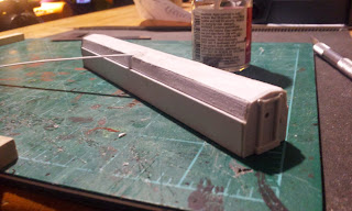
This morning I managed to do some more work on the passenger sharks. I finished the basic shell of the B unit, removed the panel seams from the one A unit and sanded all three. I hate using anything less than #400 because it tends to leave nasty scratches in the work, witness the marks shown here...
Scratches From Sanding

So after I removed the seam detail from the A unit and finished patching a slight defect in the B, I set about "restoring" the finish on the three shells. I used a silicon carbide "sandpaper" that is used in the auto industry for finishing paint. It's waterproof so it can be used for wet sanding, a technique that results in a high quality finish. I used wet sanding on these three shells. The rough sanding was done with #400. For the second sanding I used #800. I finished off with #1500 a very fine grit that can polish wood. Great for finishing motorcycle "tins" (tanks and fenders).

Once the sanding was finished, I started adding the panel seams to the shells. I use strip 0.010" x 0.020" styrene strips. They may seem small, but this is N scale and even at that size the seams are still over 3" wide and 1.5" deep. I make the horizontal seams first. Instead of eyeballing the distance this time I actually used a scale measurement and made them 3' apart. I tack down the end at the cab with liquid styrene cement and walk away while the glue sets...
Panel Spacing: Vertical

I went out to the layout and made some adjustments on the styrofoam armature for Kittanning Point. I worked on the raised fill inside the curve, started the mountain to the right of The Point and Kittanning Run...
Kittanning Run


I also mocked up the actual skin of the mountain. I was going to use craft paper soaked in wall paper paste, but the wife suggested cheese cloth. She handed me a few yards and I draped it over the armature. I crumpled some tin foil that I will use as a mold of the rock face and put that in place at The Curve...
Viewing The Curve From KN

It's actually beginning to look like something...
Horseshoe Curve

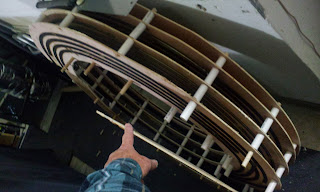
Once again I walked away while the glue set. Since it was almost lunch time I did a quick modification on the helix. I cut the dowels that serve as the uprights at the top level...
Stretching The Helix

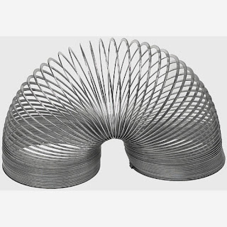
I have an idea that I want to try...While working on the track work I found that I had to raise the upper level so I could finish the connection to the previous level. I didn't think about it at the time, but it has occurred to me since that it sure would come in handy if I could do this anytime I needed. It would allow access to the various levels. Since the helix is a helical spiral it can be stretched like a toy slinky...
Slinky

I'm thinking that if I use long enough uprights I can do something similar. The levels are kept separated by 2" spacers that are not glued to the levels or the uprights They can move. If I revise the helix so the levels can also move. The spacers and the plywood would be able to travel up the uprights...
Expanded Helix
The drawing is rather crude, but you may get the gist of the idea. I don't expect it to open as wide as shown, just expand the helix to some extent, at least enough to work on track or retrieve a derailed train.

Won't know until I've tried it.

Regards,
Frank Musick
Building a dream layout on a nightmare budget
The Allegheny Eastern Railroad


Friday, November 15, 2013

The Shark B-Unit

Being retired gives me an advantage over most other model railroaders. I get to spend at least eight hours a day on something I love doing. So I get to work on many different things on the days I devote to the hobby. At present I'm working on scenery, an improved design for the helix and a set of Baldwin DR-6-4-20 passenger "sharks".

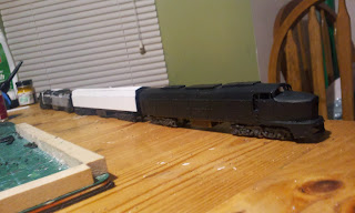
This past few days I've been working on the B unit. I built it from scratch because I had run out of complete shells to kitbash AND I wasn't happy with the how the two A units came out. Splicing two bodies creates some challenges especially when the shells have different makers and plastics.

On the B unit I built the sides and top out of a single pieces of plastic so there is no joint in the middle I did use the ends from V-Line shells that were in the scrap pile. These ends also served as templates for the body parts. It went pretty well although I had some problems with the roof. I carved a bit too deep and had to patch it with plastic strip left over from the build. I basically kept adding plastic and welded it in with styrene cement...
B Unit Patch

I used the frame from a dummy Alco PA model. Like the powered PA models I used the trucks can be "spun" around on their pivots to create the longer wheelbase of a Baldwin shark.

At this point I have three units, an A-B-A set that still needs a bit of work...
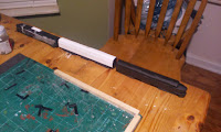
PRR Class BP3, Baldwin DR-6-4-20 A-B-A Set 

They look okay, but like I said earlier, the kitbashed A units don't quite look right. I sanding the center seams I went too far and the lines aren't as clean as they should be. Rebuilding them using the construction I used on the B unit would go a long way in improving their looks... 
Passenger Sharks!

At present they are passable at a distance but close examination reveals the faults in the finish. Despite the flaws, they look enough like BP20's to be photographed on the layout.

Painting and detailing is still in the future. My experience with N scale decals is limited and an attempt to stripe a PA set left a lot to be desired. I'm gonna try again. Hopefully I can do better.

Regards,
Frank Musick
Building a dream layout on a nightmare budget
The Allegheny Eastern Railroad


Thursday, November 14, 2013

Taking The Scenic Route: Part 5

As I mentioned last entry I dropped the arch method of mountain building and went with a different idea.

One of the cooler things I learned modeling for train simulators is that you can use real world data to create your digital world. Geo-spatial data can be imported directly into the program. The software uses the information to draw the landscape the trains will operate in. The result is close, within three meters in most cases. There is no selective compression. For all intents and purposes the mountains and valleys in the sim are the same size as the reality.

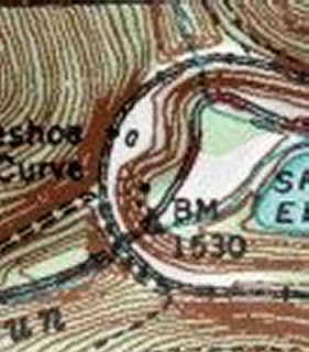
While the digital world in my computer may have enough room to model Horseshoe Curve full size, the Allegheny Eastern does not. As in most model railroads selective compression is the order of the day. Horseshoe Curve is about four feet across. The mountains around it are reduced in proportion to that measurement. I had hoped I could create a scaled down printout I could trace but that proved beyond the memory limits of my PC. I can consult topographical maps but I can't use the information directly...
USGS Map

So I had to approximate the lay of the land. The first thing I did was measure the scene. These dimensions were marked out on a sheet of blue foam. I also made a tracing of the roadbed on craft paper...
Roadbed Tracing

I used a tailors tracing wheel to transfer the roadbed shape to the foam. Using the information from the map and the layout dimensions I sketched contour lines, waterways and the reservoir around the roadbed...
Sketching Contours

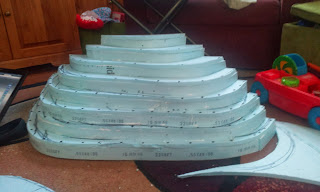
The next step is to cut the foam along the contour lines. Each piece of foam from the cuts becomes a level on the mountain. On the USGS map the major lines indicate a hundred feet, in N scale it's about twenty five. I separate the "levels" with the same 2" high strips that I used for the roadbed. The parts are fastened together with tacky glue and pinned in place by drywall screws. I built the rough shape in the family room...
Kittanning Point
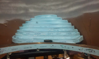
I installed the "mountain" on the layout. The thing is mounted on foam risers to bring it up to the same height as the track. I set one of the freight sharks on The Curve for reference...
Horseshoe Curve

I still need to add some height and the craft paper "slopes" to "The Point" as well as the adjacent slopes and the landscape below the tracks. It's not as high as I had thought it needed to be, but it does dwarf the locomotive. Hopefully I'm going in the right direction.

Regards,
Frank Musick
Building a dream layout on a nightmare budget
The Allegheny Eastern Railroad


Wednesday, November 13, 2013

Multitasking

There are a few irons in the fire right now, all layout related but in very different directions.

Ever wonder what is meant by "ground foam"? I've seen it mentioned over and over again in magazine articles. I think it's generally assumed that everyone knows what ground foam actually is. For those who, like me, were never totally sure I thought I'd show my version of the stuff. I started with floral foam. The craft store sells two kinds. One is a kind of spongy dark green styrofoam and is not the stuff you want. The other is light green (sea foam) fine grained carvable foam that holds moisture. The latter is the foam I used. Costs about $2 for a 8" x 3-1/2" x 2-3/4 block...
Floral Foam

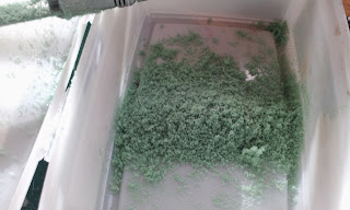
To grind it I just ran a file over it. It makes a very fine, light fluffy powder...
Ground Foam

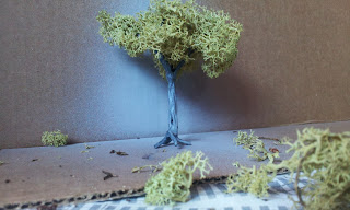
I took the tree I made in the last entry and pulled the reindeer moss off. I sprayed on some tacky glue thinned water and dish detergent. I dipped the lichen/moss in the ground foam to make thicker foliage...
Foam Coated Reindeer Moss

I added the moss back to the ethertree armature and arranged it so it resembled a real tree...
Finished Tree

Yes, the tree can stand on it's own. Those roots come in handy.

Another area in the works is the topography at Horseshoe Curve. I tried the "arch" approach but wasn't happy with it. Eric, one of the fellows at Railwire, suggested I use the nested contour method I had outlined in "Taking The Scenic Route: Part 4"...

Nested Contours

Nested Contours Section


Eric pointed out that stringers weren't necessary and I might use dowels for uprights...


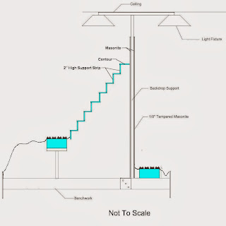
You would think it would be obvious to me, but my brain doesn't work that way. I thought I might use PVC pipe instead of dowels. I kept thinking on it and it occurred to me that I could combine two methods and get the same results. If I use the nested contours and support them with 2" high strips I could shape the strips to match the contours...
Cross Section: Horseshoe Curve

Haven't started the physical work yet so I don't know how it will work. The "steps" will be covered with craft paper to make a smoother slope.

I've also started work on the passenger shark B unit. Except for the ends, which are cut from V-Line scraps the shell and frame will be scratchbuilt from plastic. The trucks are parts from one of the DL109 mechs I was going to use for these models...
B Unit Beginning

Regards,
Frank Musick
Building a dream layout on a nightmare budget
The Allegheny Eastern Railroad


Tuesday, November 12, 2013

A Horticultural Experiment

From reading countless articles in model magazines I know that there are about a billion ways to model trees. They range from buying a ready made tree or tree "kit" all the way to using actual plants. For budgetory reasons I avoid the ready made route. The model Alleghenies are covered by hundreds of trees. This translates to hundreds of dollars that could be spent on track, motive power or rolling stock.  So I keep looking for the kinds of plants that make good tree models. Haven't found anything that suits me so I'm still looking. The floral departments of the craft stores we frequent don't help. They don't carry real plants.

Some of the other methods to model trees involve twisting wire into tree shapes and gluing lichen or other materials to simulate the leaves. Twisting wire into tree armatures seems time consuming, especially when you need an untold number. Once you get the armature made you have to cover it with clay or some other substance so it doesn't look like twisted wire.

Having worked in the computer industry for a couple of decades or so I'm pretty familiar with twisted wires. I've spent a fair amount of time untwisting them while making network cables. Among other things I've learned that it is much easier to untwist wire than it is to twist it. The Ethernet cable used to create computer networks comes ready twisted. It's like a long string of tree armatures waiting to be released.

I'm probably not the first person who has thought of this. It's pretty obvious if you are familiar with twisted pair cabling. The cable I used was a 6' CAT5e "patch" cable used to connect a computer to a wall outlet or a router to a cable modem. I purchased mine at the local Walmart...
Ethernet Patch Cable

You can buy this stuff in bulk, but the longer patch cables will provide quite a few tree armatures.

I cut off the ends and toss them. Won't need them and can't reuse them. I then strip away the insulation from a short section by splitting it with a razor or knife blade. The insulation could be left on for larger scales. I feel that it makes the trunk of the tree too large in N scale . I only remove the insulation from the section I'm working. It's handy for keeping the pairs together until I need another section...
Removing Insulation

Some cables have a second layer of insulation that looks like tin foil. I tend to leave this in place. It helps keep the wires together and doesn't add much to the thickness.


I cut the section to the length I want. The pairs tend to unravel after the insulation is removed so I give them a couple of twists to tighten things up. I then start untwisting short lengths of the pairs to make "branches"...
Ether Branches

I untwist even shorter lengths at the other end to create "roots"...
Ether Roots

Finally I dip the entire section in Plasti-Dip. It's used for coating tool handles and is available in home improvement stores. I let the "tree" drain a bit back into the can. In a few minutes the plastic cures and Voila!...
Ether Tree
Although Plasti-Dip comes in a variety of colors the store usually only carries black. This isn't really a problem. I hit the tree with a few light shots of gray and the black adds extra dimension to the trunk...
Painted Tree

I throw on some reindeer moss to fill out the foliage. I use reindeer moss from the craft store. It's cheaper then the lichen they sell for models. I've also harvested my own lichen when I was visiting the Seattle area. You can get pounds of it free...
A Tree

Just a tip...The Plasti-Dip has a rather short shelf life once the can is open. The lid is plastic and doesn't close airtight. I pour it into an empty paint can and close the top. The paint cans are also available at the home improvement store.

Regards,
Frank Musick
Building a dream layout on a nightmare budget
The Allegheny Eastern Railroad


Monday, November 11, 2013

Taking The Scenic Route: Part 4

One of the members of the Railwire forum, Dave Foxx, posted a comment after I posted a photo of the mock up. I hope Dave doesn't mind if I quote him here, "I'm not so sure that I would be concerned with the height as much as the slope.  Figuring that most people will be focusing in on the trains, it isn't as important to get the overall height right as it is the slope.  In other words, space looks tight for you, so the higher you go with the mountains, the more vertical your cliffs need to be.  If they are completely vertical for the height you're talking, I don't think that you will capture the look and feel of Horseshoe Curve.  I would recommend cutting back the height and focusing on getting the slope correct.  That's the risk of modeling a highly recognizable area, like Tehachapi and the loop.  You have to get it right."

After sketching Kittanning Point directly on the backdrop I realized that Dave was absolutely right and I had forgotten one very important thing. Horseshoe on the layout is less than half the size it should be. If it was to scale it would be over ten feet wide. If I make it anywhere near scale vertically it would look more like the mountain in Close Encounters than anything in the Alleghenies. If the mountain is half as high, it should be half as wide. So I rethought the entire idea.

The other thing I decided was that a reasonable looking mountain would need more room. So I moved the supports back to with an inch or two of East Altoona and Juniata...
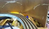
New Backdrop Location: ANTIS
New Backdrop Location: Juniata


This gave me quite a bit of space on the opposite side, more than enough to build a respectable set of three dimensional mountains...
New Backdrop Location: KittanningPoint
New Backdrop Location: KN


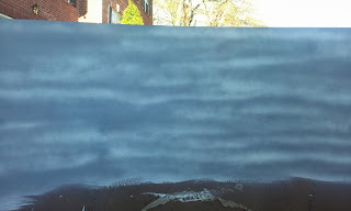
Since I was reasonably sure this is where I wanted to keep the backdrop I painted it before I mounted it. I started with a coat of Bulls Eye white primer. I didn't go for a solid covering. I let a little of the dark color of the masonite show through. When the primer dried I sprayed on Walmart gray primer. Once again I let some of the white show through. I was aiming to replicate an overcast autumn sky. I think it actually came out pretty good...
October Sky

When the paint dried I lifted the masonite into place and fastened it to the upright supports. The problem now was how to build a mountain.

I went back and looked at the topographical maps I have for the area. It occurred to me that if we can use full size trackplans to help us lay track why can't we use scaled maps for scenery. I took the scale of the topographic map and divided it by the scale I model in. If I got the math right it's map scale/model scale x 100 = % scale factor. I then reduce (or enlarge) the map in Paint Shop Pro using the percentage. It took a bit of trial and error. Using the ruler and grid function of the software I kept modifying the percentage until the map fit into the actual area on the layout...
Horseshoe: N Scale Topo
I think there are several ways to pull this off. The most obvious is to build a pile of 2" thick styrofoam and contour the sides with saw and or file. The problem here is that 2" extruded styrofoam costs $30 a sheet or better. Falling back on my old standby, 1/2" blue foam, I came up with several ideas. One is to create horizontal layers that match the contours of the map. I would have to start from the "top" or inside contour line and work my way out. The result would hopefully be a set of nested shapes that reproduce the slopes...
Nested Contours

Nested Contours Section


To make this work requires a "stringer" to support the shapes. It's similar to what a carpenter uses to build stairs. The stringers would have to match the contour they support. No two stringers would be the same. A lot of work is required.

The second would be to use the same 2" high strips I use on the roadbed. I could simply lay the foam to match the contour lines. The trouble here is that the slope is steep and not suitable for modeling the general shape of mountains found in Pennsylvania. Unless the strips overlap so they can be glued to one another this method also requires a stringer.

The third approach is to use the two inch strips as vertical "hoops" like one might find in a tent. The strips are formed into arches that match the general outline of the mountain.  No stringers are required and the slope can be adjusted in several ways. One is to widen the arch. In the case of a rock face, such as the cut at the apex of Horseshoe Curve, the arch can serve as a frame for that face. I mocked this one up because it seemed the best alternative...
Support Arches

The arches will serve as supports for one or more layers of craft paper soaked in wallpaper paste. I'm not sure if wallpaper paste will give the desired result, but it's worth a try.

Regards,
Frank Musick
Building a dream layout on a nightmare budget
The Allegheny Eastern Railroad