Sunday, April 28, 2013

Support Sunday


When I'm waiting on folks I try to keep busy, but sometimes I don't want to start a big project because they might come along any minute. To bide some time I decided to make some of those PVC supports I told you about in the last entry.

I need to make some corrections on my "bill of materials". The smaller PVC pipe, the upright, is 1/2" I.D but it's PVC-1120 SDR21 not SCH40. The PVC-1120 SDR21 is thin walled as compared to the thicker walls of Schedule 40. Same with bigger pipe, the "socket" is actually 3/4" I.D. The shelf in the store said 1".  Sorry about that...
Revised Smokejack Roadbed Support

I gang drilled both the socket and upright parts from 10' lengths of the respective pipe. I started with the sockets and laid out the 1/2" diameter holes first...
Center Markings for 1/2" Dia Holes

I used a brad point bit to drill a hole at each location. Brad points don't really need a pilot hole, the small point can be aligned to the center markings. I was careful to use a lower drill speed. Too fast and I could lose control resulting in torn pipe and/or hand...
!/2" Holes Drilled Before Cutting.

After all the holes were drilled I used a pull saw to cut the sockets apart...
Sockets Cut to Length
Once the I had cut the 10' length of 3/4" I.D. into sockets, I started on the 1/2" I.D. uprights. As before I laid out the center locations along the stencil on the side of the pipe. I then drilled a pilot hole at every other line. I wanted to cut a 10" section of pipe with the hole saw. I took my time lining up the hole saw, making sure the saw was centered on the pipe. Once all the holes were made I cut each 10" length in two, creating the 5" long upright...
Hole Saw Cuts Every 10"
10" Section Ready to be Cut in Two


I had quite a bit of 1/2" schedule 40 PVC laying about from the helix. Some of it was already cut to 2", just perfect for the 2 track roadbed. I cut some 4" lengths from a 5' section I had on hand. I then glued these crosspieces to the curved notch in the upright and set them aside to dry......
Uprights for 2 Track Roadbed
Uprights for  4 Track Roadbed


 Finally, I test fitted the upright into the socket...
Assembled Smokejack

The folks I was waiting on finally showed up. They're here to cut down what's left of that cedar tree the tornado chewed back in January. I'll be so glad to see that @#$% thing gone!

In the next installment, I'll glue up the unfinished roadbed. The supports go in once that's done and the glue sets. Then I adjust the grade and start laying ballast strip and track.

Regards
Frank Musick
Chief Cook and Bottle Washer
Allegheny Eastern Railroad

Saturday, April 27, 2013

Herdin' Cats II: Cat Wrangler

There are some things that come into your head and you don't know where they came from. Something just clicks. That happened to me today when I went out to pick up where I left off on the four track spline...
Wikes Curve and the Cat Herd.
Up until this point the spline assembling process was a jumble of strips, ends, weights, clamps and drywall screws. The screws were everywhere. I used them for holding stray strips in place and other things. The spline ended up looking like a desperate attempt to plug a hole in a wooden boat. I was beginning to continue this process when BANG! The solution just appeared. I don't even think I realized it until after it happened. I had replaced a bolt bucket that was holding the spline in place at Wikes Curve with a 3" drywall screw. Rather than run it horizontally through the foam I drove it vertically into the benchwork. Then I placed another one at the next cross piece in the benchwork. Again this was to maintain the curve radius as I built...
Cat Wrangling
I placed another screw on the opposite side of the spline strips to keep it from flapping away...
Add caption
That's when the secret that every cat wrangler must know was revealed to me. By placing the second screw on the opposite side of the spline I had effectively trapped the spline between them. I then added more strips...
Foam Strips Being Wrangled Into a Spline 

...and trapped those between another two screws. The cats...I mean, strips had no place to go but where I wanted them. From then on in the job was a piece of cake. I just kept driving screws in on either side of the spline to direct the strips and hold them together...
Like Cattle in a Chute
It was like watching cattle funneled into a chute. About the only drywall screws I needed from there on out were the two at either side of the spline. I was building four track spline as fast as I could drive the screw in. Just put the new splines in place and rein them in....
BO Tower Looking Towards Wikes

In a few minutes I was past BO tower and had laid out Brickyard Curve. The screws held the spline firm, but not so tight that I couldn't make adjustments. If I needed to make large adjustments, I could just remove the screws and drive them in at the new location. I did use a few 1" screws, but only in places where the joints fell between the big screws...
Brickyard Curve
The pace of the layout was now tenfold what it was just yesterday. I raced through Keystone toward Llyswen Yards...
Keystone and JK Tower
In no time at all I had reached the location where the passenger mains and freight mains split. The freight tracks go straight into the yards while the passenger tracks curve left past Keystone Depot and the REA freight house...
"the passenger tracks curve left past Keystone Depot"

The final run was made parallel to Llyswen Yards...
...and into East Keystone. When I reached there I realigned the tracks at DI tower. I wanted to move them farther away from Kittanning Curve and create a nice right hand sweeper...

It only took a few hours to lay out thirty odd feet of track...
GD tower Looking Towards Tunnel Hill

As I went along I realized that the "guide" screws would also serve as clamps for the glue up and assembly, thus making that part of the process much easier. All I need do is glue up the strips and then squeeze them in between the guides. This will make the assembly process quite a bit faster than it has been. The roadbed could be ready for track in a few more days (Can I get an Alleluia?).

Which brings us to several related developments.

I had been buying Woodland Scenics foam ballast strip. It was costing me about $10 for 24 feet on the average. I've recycled that stuff more than you will ever know. It's looking kind of ratty now, and I need to buy more. The wife and I were talking about this when she brought up sheet cork. I know sheet cork exists and has for decades, but it always seemed to be a lot of work to cut your own ballast strip. Especially since there are so many choices of the pre-molded stuff. That however was before ThingX had come along and taught me otherwise. The cost is phenomenal. $15 will buy you a 2' x 4' roll of 5/32" thick cork. That's enough for 96' (cut into 1" strips) of roadbed. Since the estimated length of the code 55 main line is 280 feet (4 tracks x 70'), I would only need three rolls. To make things even better, I can buy the stuff at 40% off. I can also get thinner cork (3/32") in a larger roll for the same discounted price. That's a 36" x 96" roll or 192 feet of ballast strip. Two rolls should be enough for the mainline. Sorry Woodland, don't think I'll be needin' your scenics anymore. At least not the ballast strip.

I also came up with a idea for roadbed supports. The wooden ones I was thinking of using are simple enough, but machining the adjustment slot on at least 70 supports is a bit of work, especially if you don't own a drill press or a router table. I could make another router table (I disassembled my wood working bench to build the layout), but I would have no room for it in the garage. So this design...
Wood Roadbed Support

Has been replaced by this design...

They are really simple to make and require only a handsaw, a drill with a 1/2" Brad point wood drill bit, a screwdriver and some PVC glue. A 1/2" hole saw would be handy too. I made one up with one or two ideas in my head and came up with a third...
PVC Roadbed Support Socket
At first I thought of conduit clamps to hold the 1" diameter PVC pipe. Too many parts. Then I thought of the split pipe mount that you see at the bottom with the three screws. Too much work, too many screws and no stability at the split. The third idea is what you see at the top. I drilled a 1/2" diameter hole, big enough for the head of a lathe screw to pass through. The brad point on the drill puts a pilot hole for the screw on the opposite side. I then inserted the screw with a screwdriver and tightened it up. This fastened the 1" PVC pipe, or "socket" solidly to the 2x4 bench work.

I took a 5" length of 1/2" diameter PVC pipe or "upright" and slipped it into the socket. Because of the lathe screws the pipe fit snugly in the socket with no play. Rather than have the roadbed balance on the top of the upright I wanted a crosspiece for the roadbed to rest on. There were a few ways to do this. I chose to cut a semicircular chunk out of the upright at the top. This serves as a saddle so that an appropriate length of 1/2" PVC pipe can laid across there and glued in place with PVC clue. When I "mass produce" them I'll use the hole saw before I assemble the parts. It's less awkward...
Smokejack Roadbed Support
Since the goofy thing ends up looking like one I christened it "Smokejack". The support has infinite adjustability between 0" to 8". Once they're adjusted I will drill a pilot hole and drive another lathe screw through both pipes, locking them in position. They are so easy to make you could put one together in less time then it took to write about it. All I need now is 70 or so more.

That's about it for this time around.

Regard,
Frank Musick
Chief Cook and Bottle Washer
Allegheny Eastern Railroad

Friday, April 26, 2013

Herdin' Cats

I started this morning around 9:30. Spent a bit of time at Harrowgate adding the "extension". With 2/4 added to the benchwork I added 1 1/2" to the layout on that side. Not much, but enough. I then mucked about with  the bridges awhile, experimenting with cutting out the arches in the foam core of the spline...
Layout Extension Harrowgate/Helix

Layout Extension Curved Bridge
"experimenting with cutting out the arches"

Next I moved onto the helix and temporarily installed the top two levels. I need the approach level in place so I can move on to the next step. Laying out the mainline from the top down...
Helix from Harrowgate

The center of action at Tunnel Hill is the helper loop. All those "snappers", as Pennsy called them, have to be facing forward to head back down the hill. The rules limit their speed while in reverse, while right way round they can do the track speed limit on the way down. Anyway, the helper loop also dictates the general track layout in this area, especially the location of the westbound tracks. They are crowded between the helper loop and the Harrowgate area 8" below. The loop has a radius of 16.5". That's rather generous in N scale and it needs to be. The smallest helpers are Class L1s Mikados, but I Class and J class locomotives also get assigned to helper service. These long wheel base locomotives need some run to come about...
Tunnel Hill Helper Loop with Radius Gage

The westbound tracks run around the loop with the inner track at about an 18" radius. More than that and they would overhang the river scene below. As it is there's only about 3" horizontal distance between the two. I have to fit a mountainside in there somewhere...
"3" horizontal distance between the two"

After locating the loop and the westbound main I laid out the eastbound tracks...I moved the "radius gage" I had used for the loop and used it to lay out a 18" radius curve though the New Portage Tunnel...
Eastbound at New Portage Tunnel
I then added the tracks thru the twin tunnels from Sugar Hill. I had to work both sides on the layout. It's only a two foot reach, but sometimes it's easier to reach from the "wrong" side. It took a bit of adjustment, but I managed to get all those separate tracks to flow together. It came out better than I hoped...
Sugar Furnace
So far it's been pretty straight forward laying out the splines. They have all been one or two tracks. At SF tower they all come together. The mainline is four tracks of curving right of way from Remington all the way into Keystone. Laying out  a curved spline for four tracks is like herding cats. No other way to describe it. You are juggling eight foam strips. They all have different lengths because of staggered joints, and eight different radii. The ends are all over the place. You are curving, clamping (conventioal and screws), moving tools, supplies, bolt buckets and everything else as you go along trying to maintain the minimum radius. To enhance the fun, sometimes you can get the proper radius until you work further than the curve. The direction  and radius of the following curve affects the one you actually are trying to layout. The work goes extremely fast, if only because you are try to keep up with the serpent growing across the garage. Because the spline becomes one huge assembly whatever I do at Kittanning may effect the radius at McCains (or even Reminigton). At the same time, adjustments are a piece of cake to make. The spline flexes into whateve radius curve you want, but only if you don't fasten the strips together. They have to be able to move independently at the same time you need them to be one assembly. It's a great deal of fun, nothing quite like it and all that sort of thing. All of the curves in the photos below had to be laid out almost simultaneously. At lest it felt like it...
McCains Curve 

Kittanning Curve

McGarveys Curve

The awesome thing for me is how the curves flow into each other. I've read this is how spline roadbed works in general, not matter what it's made from. You may be able to see in the photos that each curve eases in to the next. They do. All of the curves, with the possible exception of the helper loop have easements. I didn't plan for them, they just happen...
Kittaning as Viewed From MG Tower
I stopped at Wikes curve the last(or first if your heading west) curve before BO tower. I ran out of foam strips. Some of the strips I cut from my first sheet were not the proper size. If I had cut them correctly I would have had more than enough to finish the mainline all the way to Llyswen Yards...
Wikes Curve Just a Few Feet From BO Tower

That's about it for today. I may have things to do this weekend but when I'm back to work the permanent construction begins. Once the spline is built and glue dries, I create the grade up The Hill.

Regards,
Frank Musick
Chief Cook and Bottle Washer
Allegheny Eastern Railroad


Thursday, April 25, 2013

The East Side

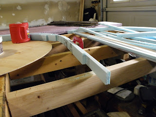
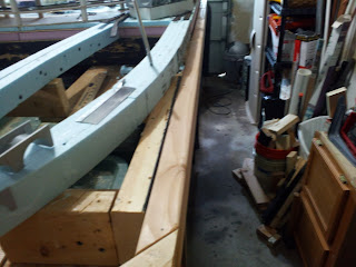
Well, almost finished. I was able to assemble the roadbed for the entire "east" end of the layout. It took about two or three hours to glue up the strips and clamp them with drywall screws. I must have used a lot of  1" screws, because I emptied a pound box. Thank God it's only six bucks a box. I also fastened the raodbed to the benchwork using 3" drywall screws driven right through the foam. I buried the screw heads into the roadbed...
Fastening the Roadbed to the Benchwork

Anyway, I learned more about making this whole idea work. I removed all the hard strips so I could get more flexibility out of the splines during assembly. The foam really is easy to work with. I was able to do all kinds of things that would have taken a lot longer in wood. The hard strips will be installed as the last step in the building process.

The mainline crosses over itself on its way into East Keystone, just as the Pennsy does in East Altoona. The flyover at EF tower allows Track 1, the eastbound freight main, to pass over Tracks 2 and 3. These tracks allow passenger trains to bypass Llyswen Yards, just as the real PRR tracks served as a bypass for the yards at Juniata. Track 4 runs directly out from the east end of the yards, passing the East Keystone locomotive facilities as it does. Track 3, having "flown" over at EF tower, joins Track 4 at DI tower in East Keystone.
Looking "East"
The real situation on the PRR was more complex (how's that for understatement). There was a receiving yard for westbound freight east of the flyover which was actually the "hump" for the westbound classification yards to the west. Westbound thru freights bypassed the hump. They went directly into the midst of Juniata yards. While I couldn't model the actual yards on either side of the flyover, I did want to capture some of the feel, including the "castle" like tower known as HOMER. The track arrangement on the layout also does away with a number of crossovers in a pretty dramatic way.

PRR at East Altoona
Farther east, the roadbed at Harrowgate is virtually complete. There is a bit of work transitioning into the helix, which is now back where it belongs on new "adjusted" base. Harrowgate is modeled after the bridges on the east side of Spruce Creek tunnel. It's the reverse of the actual Spruce Creek, but I wanted to model the bridges  that span the Juniata...
Looking "West"
I planned to use a slew of Atlas stone arch bridges here, in the "normal" way they get used. The introduction of the spline changed all that. I "modified" the bridge kits by sawing off the sides. I then temporarily glued them directly to the side of the spline...

"Modifying" Atlas Arch Bridge
 I had to think on this awhile, because I was considering gluing them to the sides of the hard strip. This would have required cutting the laminate strips in this area with a hole saw that matched the bridge arches. It occurred to me that the Atlas sides could replace the laminate in this area. Because of the opening, the laminate would have been weakened quite a bit. Structurally there would be no difference between the two so I decided to glue the bridge side directly to the foam. The spline itself will be weakened, but the same situation would exist on any other form of roadbed construction. I wanted to try to keep the roadbed continuous across the bridges rather than piece it together at the base of the helix...
Bridge #213.50
Bridge #213.50 is curved just as the roadbed, one advantage of gluing the sides directly to the roadbed. Bridge #213.10 is straight and runs directly from the east portal of the eastbound tunnel...
Bridge #213.10
 In the photos the bridges hang in space. This will change. The eastbound tracks ride right along the edge of the layout. With the previous roadbed I had to cut the benchwork to create scenery below the track. To compensate for the missing pieces I had to install an additional leg. With the new roadbed in place I intend to run new sections of 2x4 in this area. It's not just to strengthen the benchwork though, I'm adding a 3" to the layout...
Harrowgate Extension

One other addition has entered my mind, but it's more of a wish than reality. I've always liked the idea of a full circle roundhouse, like the Pennsy had at East Altoona. One of the earliest track plans included this. I gave it up because it used too much space. Something got me thinking about it again. There is some room at on the "east" side for a bit of expansion, something I call the East Keystone Salient...
Full Circle Roundhouse?

That's enough for today, time for bed.

Regards,
Frank Musick
Chief Cook and Bottle Washer
Allegheny Eastern Railroad