 |
| Going... |
 |
| Going... |
 |
| Gone!!! |
The old helix (Mark III ?) was slowly disassembled so the track could be re-cycled. For the most part all I had to do was pull out the nails holding in place. Since the some the nails were a press fit in the plywood, this often took a bit of pulling with needle node pliers. There were a few places where the track had been glued in place in an attempt to fixx problems. Fortunately I used tacky glue. It holds very well, but doesn't harden like white glue. Stays flexible so it's easier to make changes. As the track was pulled up on each level, that level was removed to gain access to the next. Took a few hours but I got the track up almost intact.
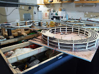
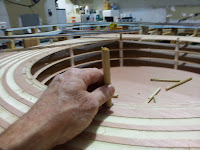
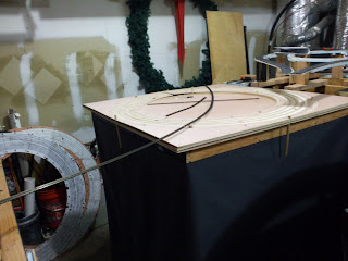
With all the routing and drilling completed the next step was to assemble the new helix (Mark IV?). One of the issues with the old helix was shoddy layout. Many of the post holes did not line up vertically and as the levels went up the posts would be forced out of plumb. Some of them actually broke as I tried to force them in place. This time I was very careful with the layout stage and it payed off. Once I got all the panels oriented properly I assembled the base and the levels reusing some posts and 2" spacers from the old helix. With most of the posts in place I then test fitted a dowel in any open holes. Everything lined up perfectly
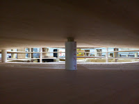 |
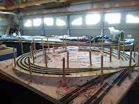
| View Towards the Center |
 |
| Test Fit |
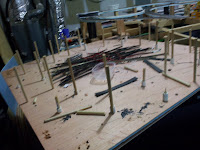
Once I was sure that everything would actually work I disassembled the entire thing and stacked the panels. I inserted posts in key locations to keep everything where it should be. I then clamped the panels together and cut the joints using a square and razor saw. Leaving the square corners on the outside created a tangent I could rest the base of the square against. It allowed me to make the cuts perpendicular to the tangent and vertically aligned.
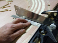 |
| Cutting Joints |
With all the woodwork out of the way, it was time to start laying some track. First I laid out track in the slots I had routed in the plywood. I counted how many sections of code 80 flex track were needed to make a complete circle for each radius and noted it at the bottom of each channel.
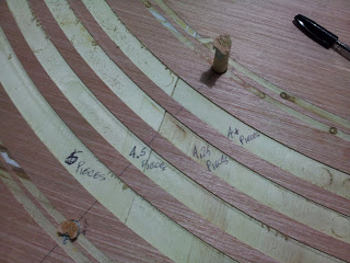 |
| Section Quantities |
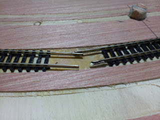
Now that I knew how many sections I needed for the curves I pulled the quantity I needed for the innermost track and got out the soldering iron. I connected the first two sections with rail joiners while the iron got good and hot. I brushed some rosin on the joiner making sure I coated the inside of the joiner and the outside of each rail. When the iron was ready I placed the tip under the joint and touched the thin solder I used between the rail and the joiner on the outside of each rail. If the iron is as hot as it should be the solder should just flow into the joint. If it didn't I would stop and make sure the tip of the iron was clean and added more rosin. I ended up with some nice looking joints. I only soldered the outside keeping the inner side clean for the wheel flanges. Some of the solder flows between the rail joiner and the bottom of the rail so it's still a pretty strong joint.
 |
| Clean Joint |
When you use flex track it is always a good idea to check which rail slides when you curve the track. This sliding rail should always be toward the center of your curve. When you are soldering your track this step is IMPERATIVE! If you don't the track will actually buckle as you curve it. If you are soldering long lengths the track WILL get unwieldy and squirm like a snake. The rails WILL pull away from the ties and wreck the track. How do I know this? Because I soldered the first two sections the correct way. On the third section I unknowingly placed the sliding rail on the outside of the curve. I soldered the fourth section and then picked up the track and laid it out. It stretches pretty close to ten feet.
 |
| A Soldered Section of Track about 10 Feet Long |
The problem showed up when I tried to fit the track into the slot. That misplaced rail let me know it was there in no uncertain terms. Several inches of rail sprung in two different directions and tore itself away from the tie strip. I had to break the joint and repair the track.
 |
| Broken Track |
Once I got that fault corrected I laid the track into the innermost slot. The slot was originally routed with a 3/4" bit that would have produced a close fit and pretty much have held the track in place while the glue dried. Unfortunately the bit was a cheap one and it burned up. I had a better bit but it was 1". I used it anyway and rerouted all the slots with the new bit. There is no close fit now, but the curve radius is wider by an 1/8". I lay the track so it presses against the outer wall of the slot and use that to keep the track in a perfect circle while I glue it down. The press fit would have been ideal, but this works just as well at keeping the track in a true curve.
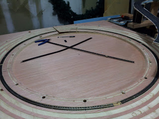 |
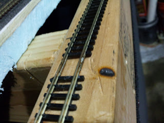
| Track Laying Commences |
Rather than lay the track on each level as I build up, this go around I'm laying the track on each level prior to assembly. The track is laid so that the rails extend past the joint. When two levels are joined the rails are trimmed to suit and joiners with feeder wires will be installed. This joint will not be soldered in order to allow the track to expand and contract with the temperature in the garage. It will also allow the helix to be disassembled should the need arise (I might move someday). The joints at the approach tracks will be handled the same way.
Better cut those square corners off at 45 degrees before I go any further...
Regards,
Frank Musick
Chief Cook and Bottle Washer
 |
| Allegheny Eastern Railroad |


No comments:
Post a Comment