I got curious. I haven't really measured the length of the mainline since February of 2012 when I marked the track plan (and the layout) with the "mileposts" measured in real feet. At that time the freight mains were a little longer than the passenger mains. The bypass at Juniata cut some of the distance. Anyway, the mainline was 70 feet from ALTO around and back again. That was before I added the aisle and expanded to another penninsula at Gallitzin. I knew I had increased the length but not by how much. So I ran my 100 foot surveyors tape down the centerline of the roadbed. The passenger mains are now about 100 feet long (almost needed a longer tape). That puts the freight mains at about 105 feet, give or take. Now I know why I underestimated the amount of styrofoam I would need.
Mind you, this doesn't include the length of the track in the helix. That's about 33-35 feet. All in all the mainline is 140 feet long. Since there are four tracks...Never mind. I'll have a coronary when I see that number. Let's just say it's a LOT. In 1:160th, however, it's almost 4.3 miles. That's quite a bit more model railroad than I dreamed I'd ever be building.
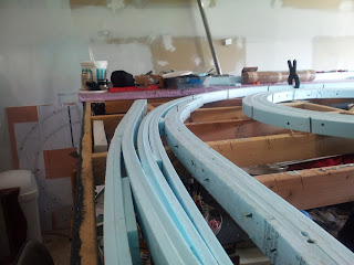
Out of those 140 feet there's about 6 feet, if that, of spline that needs be completed. It's at the East Altoona end of Juniata. When I went to connect the spline to the east side I found I could make a smoother curve there. So I did and now you get to see how the spline can be revised or repaired if necessary. In the photo below you can see the east side roadbed I built first. The passenger bypass is to the right and the freight tracks into East Altoona are on the left. The curve in between is the spline that was just finished coming east from passing Juniata yards...
 |
| East Altoona End of Juniata Slab |
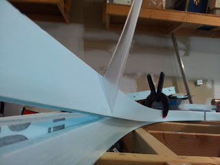
First thing to do is bundle up the new unfinished spline. I used a conventional clamp, one of my bargain table treasures. I lay the bundle on top of the older spline so I can see what needs to be done to splice the two together...
 |
| "Lay the Bundle on Top of the Older Spline" |
 |
| "Remove the Screws Properly" |
 |
| Cutting the Wrong Strip |
Now that I have cut the wrong strip I need to separate it from the rest. The screws are removed, but the tacky glue has set up for several days. I call out the heavy equipment to get the job done. The "Delaminator's" thin blade is perfect for this (and for scaling fish). I just run it between the strips...
 |
| "Delaminator" at Work |
 |
| Finally, Some Clinging Styrofoam Smeg |
The tacky glue must actually work. This stuff is stuck fast and has to be scaped off. Now need to patch the place that I cut incorrectly.. I lay a length of foam above the gap and measure off where I need to cut it...
 |
| Measuring Patch Strip |
As I'm working on splicing the strips together I realize I have missed taking the protective plastic coating off some of the styrofoam. Since the plastic may stop the glue from adhering properly I have to remove it...
 |
| Forgot to Strip the Plastic Coating |
The splice, like all the rest of the spline should have the joints staggered. Offsetting the joints maintains the splines integrity. I use the same methods for gluing and clamping here that I use when constructing any spline...
 |
| Stagger the Joints in the Splice |
 |
| Finished Splice and a Sweeping Right Hand Curve |
Two more things today and then I'll shut up...Remember when I was "experimenting with the stone arch bridges at Spruce Creek? I was calling Harrowgate back then, but hey, things round here change pretty quickly. You gotta keep awake.
I found I could cut the arches in the foam with an ordinary hole saw and a drill. I use the Atlas bridge sides as a guide. You need a variable speed drill because you want to go slow. It doesn't take much to cut this stuff and you don't want the saw to runn away and destroy the whole area. I think just the pictures will suffice to illustrate the technique...
 |
| Hole Saw Cutting Arches in Foam |
 |
| A Partial Arch |
 |
| A Plethora of Cut and Trimmed Arches |
I still need to make everything nice and pretty, but you get the idea. The curved bridge will require a bit of thought because the arches are skewed.
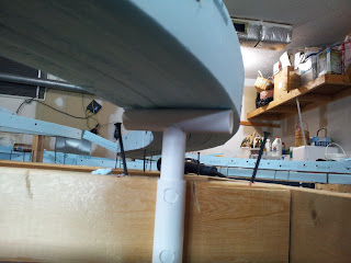
Now that I have raised the roadbed I have to start installing the "smokejacks" that will support it. The first one went in under McMains Curve and worked just as I hoped. The two holes in the socket allow me to drive lath screws through the opposite side and into the benchwork...
 |
| Mounting "Smokejack" Socket to Benchwork |
 |
| Smokejack installed and adjusted |
I didn't drive the lock screw in just yet. I won't lock the supports in position until I have the grade set correctly.
That's it for now. Have things to do this upcoming week and may be "offline" for a few days.
Regards,
Frank Musick
Chief Cook and Bottle Washer
 |
| Allegheny Eastern Railroad |

No comments:
Post a Comment