Friday, March 29, 2013

Once more into the Fray!

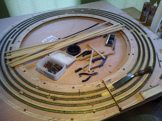
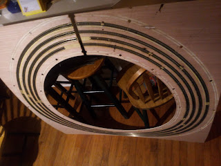
Now that the track has been relaid on all three levels of the "new" helix, it's time to start assembling (re-assembling?) the parts. I know the helix has been through so many versions that I've got everyones head spinning (including my own). That's the problem with organic design. There is a LOT of trial and error. The goal was to design and construct a helix as cheaply as possible. I think even with all the revisions, the cost was lower or equal to some other helix designs. The result is a low cost design that can repeated on a new layout. Not that I'm planning on building one again, but you never know.

Cost of building (if you only build it once)
3 sheets of 1/4" hardwood plywood at $12 ea                         $35.91
3 10' lengths of 1/2" Schedule 40 PVC pipe at $1.86 ea.           $5.58
8 1/2" dia dowels, 36" long at $0.99 ea                                      $7.92
Total expenditure                                                                     $49.41

I didn't include the flex track. I got almost all of the code 80 I used at $1 per 30" section. At real prices this would be the most expensive part of the build. I believe I used close to 55 sections to build all four tracks (about 134 feet of track). That's almost $280 at $5 each.

So for the helix parts I spent roughly what it would have cost me just to buy the threaded rod and nuts on a more conventional helix.

With all the levels ready to go, the first thing to do is create the support pins. I cut the 8 36" dowels into 32 9" pieces...
Base and Levels and Pins Stacked Prior to Assembly
I used Thing 2.0 to cut them up. It's simply an Exacto aluminum miter box with a plywood insert so I don't cut this miter box in two like the first one. By using a separate block of wood as an adjustable jig I can set the length and cut without measuring each piece...
Thing 2.0 in 2.0a Configuration 9" Cut
I then use a westernized version of the Japanese razor saw to cut the dowels into 9" pieces...

Pile of 9" Pins
With thin plywood like I'm using I need a lot of support. Each pin set is approximately 7" from its neighbor...
Supports Spaced Every 7"

With all the pins cut to size I start assembling the first level. All the spacers on the upper levels are 2" high. Between the base and the first level each set of spacers has to be cut to individual sizes in 1/8" increments.. 1/8", 1/4". 3/8" etc up to 2". I didn't use any special formula to decide what size to make each one. I just divided 2" by 16 and came up with 1/8". Every spacer should be 1/8" taller than the one before it...
First Level Spacer Sizes
With the pins and Level 1 in place things look like it's going together well...
Pins and Level 1 in Place
I added the 2" spacers that support Level 2 and lowered it onto the pins. So far so good. Level 2 fits without issues...

Level 2 Installed

The real test comes with Level 3. On the previous version of the helix, the holes did not line up well. As a result I had to "persuade" pins to fit. The application of brute force worked to some extent. I only broke some of the pins. This time, however, the holes lined up perfectly. I was able to install Level 3 with little to no problems...
Level 3 Installed
Now that I know the parts will actually fit together I can sweat the details. Have to join the tracks, add feeders and create the lower and upper approaches. Could the trains actually be running soon?

Regards,
Frank Musick
Chief Cook and Bottle Washer
Allegheny Eastern Railroad


Thursday, March 28, 2013

Antartica?

A short while ago, a fellow named Josh Surkosky started a thread on his Allegheny Division at Railwire on his hollow core door (aka HCD) layout. It's a small model pike with a big theme. Josh is modeling the Pennsylvania Railroad. You don't need an entire basement (or your whole garage) to capture the flavor of the PRR. Several other N scale modelers have managed to create the impression of the big road in a small space. Links to these and some larger Pennsy layouts can be found at Keystone Crossings one of many online repositories for all things PRR.

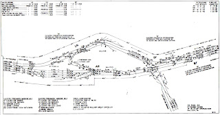
Anyway, the point of this epistle is how that discussion thread affects the Allegheny Eastern. Josh asked for input on his initial layout idea. He was attempting to create a track plan based on the PRR trackage at Gallitzin Pennsylvania...
PRR Track Arrangement, Gallitzin Pennsylvania
Replies to his thread brought suggestions on changes he should make to better represent the area in question and the Pennsy itself. While the discussion was very helpful for Josh, it also provided a solution for me. Model railroaders as a species tend to pick up ideas where ever they find them and I'm no different. Dave Smith posted his idea of a plan that suggested ways to model PRR iconic scenes in the 26 square feet Josh has available. His depiction of the wye at Cresson was simple and didn't require a lot of space, just one corner of the HCD. This started me thinking...

When I added the additional square footage to the All East, I decided to sacrifice the large area that was Gallitzin. This area included some trackage for an operating New Portage branch...
Gallitzin February 4th 2012
I extended the benchwork and at the same time created two penninsulas separated by a two foot aisle...
Same Area  Today
Aside from compressing Gallitzin (now Tunnel Hill) into half the space, I also abandoned the idea of modeling a part of the New Portage branch and the junction controlled by SF (Sugar Furnace) tower.

Dave's drawing made me realize I could still model the Sugar Furnace scene. If I took his idea for Cresson and adapted it to the All East, I would be able to "suggest" the junction. Unlike the previous version which actually had an operating scheme and small staging yard, the new version would be cosmetic.

The junction at Sugar Furnace is a bit different than the trackage at Cresson. Rather than a straight forward solution like the wye, the Pennsy engineering department had to create a flyover. This allowed the New Portage tracks to pass under the eastbound mains and connect to the westbound. At the same time they had to connect the eastbound tracks to the branch.
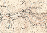
Topo Map of Bennington PA
Topo Map of Cresson PA


You'll probably notice something odd about traffic flow on and off the branch. It is odd. Be that as it may, since all I am creating is the illusion of the junction at SF, traffic direction doesn't matter.

So back to Dave's interpretation of Cresson...
Dave Smith's Representation of  Cresson, Upper Left Corner.
You can readily see how Dave has suggested the Cresson wye and branch without actually creating either. On the Allegheny Eastern Sugar Furnace can be represented the same way. There is, however, a problem in modeling Sugar Furnace. I have found very few (if any) photographs taken at SF tower and certainly no aerial views so I've had trouble visualizing the site.

Then one day I was looking through a website that features 3D digital train simulators. I had been involved in this kind of modeling and I still keep tabs on what is going on. I came across images of a 3D "route" created by a guy who is apparently stationed at Vostoc Base in Antartica. His virtual model railroad represents the Pennsylvania Middle Division and fits on a computer (there can't be a whole lot of room where he's at). If you get a chance make time to read the entire thread. Look for entries under the name cascaderailroad. The route contains scenes long gone from the Pennsy. ALL of the Middle Division is there, including parts that were abandoned before World War II...
Kittanning Point on the PRR Middle Division for Trainz
Among a lot of other awe inspiring things I found screen shots of Sugar Furnace. Since the route was under construction the scenery hadn't been completed yet. The New Portage junction was clearly visible. What's more, it was pictured from both directions.
Sugar Furnace Looking West
Sugar Furnace Looking East


How accurate are these images? Here's a screen shot of the modeled terrain, which is constructed using geo-spatial data from satellites...
High Resolution Terrain Created From Data

High Resolution Satellite Data for Horseshoe Curve


The data set he used is the same stuff used by professionals to map the earth in 3D. The detail is so fine it can show the roadbed for the tracks, roads and rockfaces. I'm pretty confident this guy is not fooling around.

 Anyway, based on his images I revised the track plan to include SF tower and the junction...
Revised Allegheny Eastern Track Plan March 28th, 2013

Actually building this scene presents other challenges, the most difficult being the flyover. The branch tracks will have to drop fast in order to realistically clear the flyover on the eastbound mains. Those mains themselves can be raised a bit. All my information indicates that there was a vertical separation between the two sets of mainline tracks. By lowering the branch while raising the eastbound main, I should be able to finagle enough room to park a train there, waiting for a clear signal that will never happen.

Regards
Frank Musick
Chief Cook and Bottle Washer
Allegheny Eastern Railroad


Monday, March 25, 2013

Alrighty Then

Finally I can report some actual progress. I'm up to level three on the helix! Using some advice from Dave Smith at Railwire I also mastered soldering the joints on the steel Rapido track...
Level 2

Level 3 Underway
Joint using the DKS method

I know it's not earthshaking, but it has taken me a while to commit enough time to the project. I actually stayed with it for an entire 8 hours yesterday. Level 2 is done and I started on Level 3.

Makes me wonder if other model rails experience this. You haven't lost interest, but it seems like you find other things to keep you occupied. Not in the sense that you are busy, you just find yourself avoiding the issue. I know that John Allen had similar experiences while building the Gorre & Daphetid, it's mentioned in the Kalmbach book. If the "Great Poobah" hit a slump, I'm pretty sure it must be a common occurrence. There are times when I enter the garage and wonder, "what was I thinking?". I can imagine John doing the same thing. There must have been times he got to the bottom of the basement stairs and wondered.

It's not that the task is overwhelming. Any project is just a series of manageable steps (most of the time). The Allegheny Eastern just has a lot of steps. Since there is no real timetable for completion there are no deadlines. I would like to finish before my funeral, I'm pretty sure I can't take it with me. It would be nice to get the trains moving again and that shouldn't be too long (yea, right). Everything else might be a long time coming. Altoona (aka Keystone) wasn't built in a day.

As troublesome as these "pauses" in progress are, they almost always lead to improvements in the layouts design. It was during this last pause that I discovered the Sanford maps for the towns on the layout. I now know more about the sidings and industries that were served. This will require some modification of the plan, but ti will lead to some interesting operation. Furthermore, because the Sanford maps were from 1910 or so, almost all the industries were served by rail. This "backdating" creates switching opportunities. The crews (aka me) will be kept on their toes trying to perform their duties while avoiding the heavy traffic the Pennsy was known for.

The pause also revealed some issues I hadn't thought about. The curtain, for instance, that hides the storage under the layout doesn't work. This is particularly true in the "alcoves" at Horseshoe (aka Kittanning) Curve and Bennington (aka Remington). The idea was to be able to access the storage just by moving the curtain aside. The curtain is one continuous length of fabric. It needs to be in sections (and hemmed) so it can actually move out of the way. I can hear everyone saying "well, duh...yeah!). I mentioned before that I oft times miss the obvious.

I also found that some of the benchwork doesn't hold up. Along the approach to the curve I threw in some lumber to extend the real estate. Those pieces came off when I was retrieving some of the multitudinous Rubbermaid containers (the only intermodal freight the All East handles). While it did not affect track work, it would have affected scenery, especially if one or more grand kids decided to hang off it.

Not all was serendipitous, however. There was an incident where some of the benchwork at Altoona was "rearranged". Although most of the layout sections are equipped with wheels, they are not really portable. The entire assembly is bolted together with very large fasteners. While this makes it sturdy enough to withstand most stress, it is not quite equipped to be towed. I won't bother you with droll details. Suffice to say it involved a trailer, a 16 foot boot and some rope. That little Ranger of mine may not be the most powerful truck Ford made, but it can get the job done. Haven't fully accessed the damage yet, but it seems confined to the section joint near ALTO (aka KEY aka JK)

The ALTO tower reference brings to mind another effect of the "pause". After looking over several track charts I realized that the tower names, like the beloved ALTO and others, did not come into use until after 1941 (or there abouts). On the Middle Division chart for 1925, there is no ALTO. The two towers at that end of Altoona were designated JK and BO. It appears that there were two towers a little further east labeled FG and GD. On the 1945 chart for the same area these four towers are named SLOPE, ALTO, WORKS and ROSE. SOUTH tower just east of WORKS and ROSE doesn't show on the 1925 document. ANTIS, on the east end of the Altoona installion, was designated EF. Although I can no longer find it, I believe I had a chart of the area from 1940 or so that shows the older designations still in use. Anyway...I decided to use the older designations on the Allegheny Eastern. The newer designations will only be used as a reference for folks trying to keep track of all these changes...
Allegheny Eastern Plan March 25th 2013

One more change coming into affect is in the Spruce Creek (aka Harrowgate) area at the foot of the helix. I wasn't quite satisfied with the short bridges in this location. The Juniata River is a bit wider than previously represented. The All East version was more like a creek. I removed the roadbed and widened the gap about a foot so I could put in healthier length of arch bridge in each direction. I also intend to straighten the track across the bridges...
Harrowgate (Spruce Creek)

The scene is "juxtapositioned". The bridges actually cross into the tunnels on the east side of Short Mountain, whereas they are on the west side on the All East...
Spruce Creek USGS Topographic 1931
I usually try to keep the orientation of the locations the same as the prototype, but the addition of the helix forced an "exception" here. If I could I would like to model the way the westbound tracks cross the river twice while the eastbound mains stay on the southwestern bank. Don't know if I can within the space available.

Well that's all the news from Keystone, Pennsylvania, where all the women are strong, all the men are good looking, and all the children are above average....Oh wait, that's Lake Wobegon. Sorry Garrison.

Regards,
Frank Musick
Chief Cook and Bottle Washer
Allegheny Eastern Railroad


Monday, March 18, 2013

Chasin' Sanborn

Sorry about the pun in the title, but it's literally the truth. I have been chasing Sanborn insurance maps for quite a while now. In the past I found that...
A - You have to be someone who belongs to an organization that needs the maps for commercial use (sort of like trying to get your own credit report). Some universities also have access.
B - You can pay for the maps. I'm not sure how much the maps are, but since Altoona proper requires possibly hundreds of such documents, I imagine it can get very expensive very fast.

Just this week I was searching Tumblr for images of the Pennsylvania Railroad. You'd be surprised what sorts of images you can find on Tumblr...but I digress...Among the Pennsy images I found was a piece of a Sanborn map. I followed the link and to my surprise, tripped over a FREE source of Sanborn documents. For those who would like to check them out they can be found at the Digital Map Drawer page of Penn State University's web site. I'm not sure if they cover any state other than Pennsylvania. I found what I was looking for and didn't search any further. I'll bet other universities in other states have similar web pages.

There may be some readers who don't know what a Sanborn map is. They were/are produced by the Sanborn Company for insurance companies. They give all kinds of information pertaining to structures that a company might have to insure like dimensions, number of stories, building materials, etc. They are very accurate and drawn to scale. They also include information model railroaders can use...What better way to model a town than knowing exactly how the town is laid out?

The maps I found at Penn State are not current. They are "historic" maps. All the ones I use were created in and around 1910. While this is decades before the 1949 setting of the Allegheny Eastern, towns in the mountains of Pennsylvania don't change much. A building that existed in 1900 probably still stood in 1950. It may have a different occupant, but chances are it's still pretty much the same as it was a half century before. I'm thinking this is probably true of any city or town in the mid 20th century.

Anyway...It's easier to show the kinds of info these maps contain than it is to describe....
Sanborn Insurance Map Altoona PA Sheet 45 1909

Sheet 45 covers the area around ALTO tower as it appeared in 1909. Back then it wasn't designated "ALTO", I believe the tower was named JK, one of two interlocking towers between mileposts 236 and 237. Here it's only referred to as "switch tower". The map shows the street names, street addresses and even paving materials as well as the water lines below (so we know where to put our N scale manhole covers). The PRR main and departure tracks are shown as well as the branch to Hollidaysburg (labeled "Petersburg" here) and several sidings. The sidings serve multiple customers, which would make interesting operation for a model railroad, but was probably a headache for the real PRR switcher crew. Studying these maps gives you a whole new insight on how things work. I've already seen several ideas I would like to incorporate into the Keystone area of the layout. Notice that there are several industries served by wooden trestles in close proximity. They include a curved one that enters the building occupied by Canan Knox Supply Co. Canan Knox is actually reached by two sidings, the one being shared by Altoona Concrete & Supply Co which is also served by a wooden trestle.
Sanborn Insurance Map Altoona PA Sheet 50 1909
Sheet 50 shows the area around the Altoona train station. The train shed, including the construction materials are shown in front of Logan House, the railroad hotel directly adjacent to the station still standing in 1909. East of the trainshed is the Altoona Freight House, sidings and platforms. Across the PRR main line are the buildings of the Pennsy machine shop. South of those you can see the Public Market and Mt Carmel Roman Catholic church. With maps like these I no longer have to guess at what the city of Altoona looked like. I can see the general layout in great detail.. It provides information that can used to create detailed backdrops that fit with the foreground models.

Sanborn Insurance Map Gallitzin PA Sheet 3 1910
I found maps for other areas of the layout, including Gallitzin and the tunnels through the hill. This map sheet, from 1910, shows a wye as well as sanding facilities. There is also a siding for the "Locomotive Ho". I'll leave the purpose of that structure to your imagination. The map clearly defines the street and building locations. Once again this information can be used to model the town and create backdrops that complement the models. The maps also create switching opportunities. On sheet 5 of the same set there is a siding for the M. Shultz Lumber Yard. There is also a power house, the Gallitzin Electric Light Plant, that required a siding for coal deliveries.

There are many more sheets for Altoona and Gallitzin. I also found some for the Juniata area east of Altoona proper and Bellwood. They cover various years from the 1880's to the 1920's. Granted, none of the maps so far are from 1949, but there is plenty of information to make a believeable model. Since the layout is freelance, I have lots of wiggle room.

Regards.
Frank Musick
Chief Cook and Bottle Washer
Allegheny Eastern Railroad


Monday, March 11, 2013

Two Steps Forward


After a few weeks of confusion construction is moving forward again, albeit slowly. As I mentioned before I pulled up all the track. I managed to re-lay Atlas code 80 on the first level of the helix. I believe this is version 4, but I've lost count.

I was just reading the latest issue of Model Railroader and realized I was missing out on the commercial value of my blog. Using MR articles as a pattern I thought I might make my blog more appealing to advertisers...

To construct my helix I used 1/4" plywood manufactured by Canadian Plywood LLC. I routed grooves for the track using a router sold by Sears under their Craftsman brand. I made an "adjustable" router base from the plywood by using a Ryobi drill to predrill several holes. These holes allow me to change the center of the groove so I can route the various radii used in the helix. I then cut out the overall shape of the template using a Black and Decker jigsaw.

After creating the grooves, I moved the helix parts into the kitchen so I could lay the track from a comfortable sitting position. I placed the helix panels on the kitchen table, which I had purchased from Stan's Second Hand Boutique. Sitting on a chair I also purchased from Stan's I turned on the kitchen light by using a wall switch provided by Square D. This switch is wired to an overhead light fixture using Nomex brand 14 ga wire. I made sure the fixture was equipped with a fresh Sylvania 75 watt bulb before attempting any construction work.

I used wood glue manufactured by Titebond and sold at Lowes (and other fine home improvement centers) to fasten Atlas code 80 flex track to the plywood. After gluing the first section to the plywood, I used track nails from Model Power to hold the track while the glue sets. I placed the Atlas code 80 rail joiners on the rail ends and attached the next section. I applied acid flux from Aaeon Flux using a Fuller Brush company #4 brush. I then soldered the resulting joint using The Solder Guy Incorporated's #000 solder. I let the joints cool and glued the next section into the groove. Using this procedure I was able to complete level #1...
Level 1


Enough of the tongue in cheek. Don't know how MR does it. Seems to take something out of the narrative and requires too many extra words. It's a wonder each article doesn't require an entire magazine. They'd have to drop all those real advertisements.

Anyway, working on level 2 has been a bit of a challenge. I'm using the old Rapido flex track. It's code 80 but it appears to be steel rather than nickel silver. David Smith from Railwire (another name drop) had informed me that Rapido's other track products were steel. Seems like they went the same way here. The stuff does not take to solder well. You can create a joint, it takes a LOT of solder. It's almost like you have to fill the rail joiners to make the joint. Even then the joint may not be solid. You can see by the photos that you burn up the plywood (and tie strip) more than anything else. Just as I mentioned above, I glue each section down with Titebond and "clamp" it with track nails til the glue dries. I then pull up the the nails and reuse them on the next level.

Rapido Rail and Atlas Joiners
Burned Plywood


When I'm bored with the track laying I fool around with building the N5e cabin car or the centipedes. I bought a "Northeastern" style caboose that looks somewhat like the N5e...
"Northeastern" Style Caboose
The window spacing looks to be close enough to make a passable model. Since the car was welded I'll have to remove all the rivets and some of the details. I gonna try to "kitbash" the cupola using the parts from the N5c kit I started with.

I purchased another cheap Bachmann DD40 on EBay and promptly removed the trucks when it arrived I now have the parts for a set of centipedes...
Potential Set of Centipedes

Although SAL and NdeM ran the big Baldwins as single locomotives, the Pennsy ran their's as a draw barred set, never separating them. They were scrapped in pairs. They were purchased as 6000 HP passenger units, which is what I'm modeling, and held that roll for a few years before being derated to 5000 HP and assigned to freight and helper service...

PRR #5830 Class BH50
PRR #5827 Class BP60


They worked several grades on the PRR, including the East and West slope of the Alleghenies and the Belmont Plateau just west of Philadelphia.

I tossed the shell I had cobbled together in the trash. No point in even trying to save it for scrap. I'm hoping I can make a new shell that will capture the impression of these mammoths.

Still working on Level #2 and hope to make some real progress over the next week.

Regards,
Frank Musick
Chief Cook, Bottle Washer and Director of Advertising
Allegheny Eastern Railroad


Sunday, March 3, 2013

Ad Nauseum

About a year ago I shut down the original Mile Post 15 blog. I had some reason for doing so, and that reason is gone now (Ah a mystery!). I thought I had deleted the blogs and regretted doing so, thinking they were gone forever. After 90 days (I think) of deactivation Google deletes any blog. I naturally assumed that I did not keep a backup of any kind. I usually forget to do such things.

I was wrong. I'm smarter than I give myself credit for. I did have a backup and unfortunately for the readers, Google allows the import of the backup file.

The blog was a continuation of a series of articles on my website www.kelticsylk.info. I've been recording the progress (or lack thereof) of the Allegheny Eastern since 2007. Between this blog, the Layout Engineering Reports on Railwire, and the website you can pretty much find a "comprehensive" history of the evolution of the All East. Documented for all to see are the triumphs and tragedies, forward strides and downhill tumbles of designing, building, re-designing, re-building ad nauseum of the Agg. It's a detailed account of how many different ways one man can waste a perfectly good garage.

In other news, I'm still working on the helix. I finally listened to some of the advice from other modelers and decided to use a more permanent fixative for the track. While the diluted tacky glue might work for holding ballast (we shall see), trackwork may not be a good application. I decided that it would not withstand the years of expansion and contraction the layout will be exposed to in the garage. I pulled up the track, very easily I might add, and relayed it with Titebond, a glue used for wood work. It's a bit tougher than plain white glue and somewhat water resistant.


So while you wait for the next installment and some real progress you might want to waste some time perusing the past...The restored blog entries below, the Railwire threads Here and There, or the All East progress reports at the website.

Regards,
Frank Musick
Chief Cook and Bottle Washer
Allegheny Eastern Railroad