Showing posts with label New Portage. Show all posts

Wednesday, January 18, 2012

Various & Sundrie

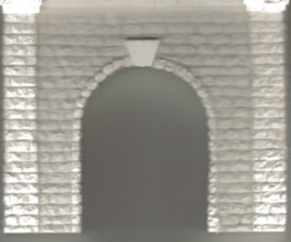
Scan of Tunnel Portal
Now that trains are running again I started working on some details. First up were the bores through Tunnel Hill. I used Woodland Scenic cast stone portals. They look the most like the Pennsy portals I remember around Philadelphia. I took one of the castings and scanned it into the program Paint Shop Pro that I use for graphics. I then copied a section of the scanned stone work to a new image to create a graphic representation of the inside of the tunnel. I pasted the copy several times until I had a six inch long section of tunnel wall. Using some of the image manipulation tools I created "shadows" in different shades ranging into black. The idea was to mimic the inside of the tunnel and the graduating darkness you would see further away from the entrance.

Tunnel Interior Wall
Since my tunnels are only about six inches long I had to compress the effect. Once I thought it looked reasonably convincing I printed the completed wall section out on card stock using a laser printer. I then cut out the wall sections and glued them to heavier cardboard.

Assembled Tunnel


I fastened the "walls" to the portals using basswood  blocks and tacky glue, making sure the walls were flush with the portal openings.  I went the "good enough" route and didn't worry too much about lining up the courses of stone. I'm trusting that as long as the train looks like its entering a tunnel the viewers imagination will fill out the details. I also did not create "roofs" for the tunnels. I wanted to be able to access the inside "just in case".

The twin bores, Gallitzin and Allegheny, just sit on the styrofoam roadbed, but the New Portage Tunnel is located where the eastbound mains climb toward the New Portage bridge. I had to construct an elevated base for the tunnel to sit on. I cut several pieces of scrap lumber to get the appropriate height and glued them with tacky glue.

East Portage Tunnel, East Portal
To the right is the east portal of the New Portage bore. The photo was taken from the eastbound track of the New Portage branch. The double tracks of the eastward main line bear off to the right.The overall effect is pretty much what I was hoping for. Even with the tunnels open to the ceiling lights they still appear to get darker towards the center. All in all, I think they'll look pretty good when everything is painted up and weathered.

Just adding these few details made a big difference in the feel of the Tunnel Hill area. It's getting easier to imagine the finished product.


Signage

There are several other items I've added that are what might be called "operational details". I made up small signs for the sides of the benchwork showing the name of each location and other pertinent information. On the left is a photo of the signs for Gallitzin. The location name is made to look like a PRR station sign. There is also a sign for the tower designation UN which controlled the westbound interlocking. I've yet to add AR, the tower that controlled the eastbound interlocking. I've also posted speed limit signs. Starting at UN headed west the passenger speed limit is 70 mph. Freight trains are limited to 35 mph, probably due to the fact that the route is all downhill into Johnstown. Don't want any runaways careening through the communities on the west slope. I still have to add speed limit signs for east bound trains. I haven't quite figured out how I want to show all this information. I'll probably have a column of signs for eastbound and a separate column for westbound. These signs are black & white. The finished signs will be color.

"Mile" Markers
 I also went around the layout with a 100 foot reel type tape measure and measured the main line. The flexible tape allowed me to follow the center of the track line, including the curves. I then marked the styrofoam roadbed at every foot. I found out that the eastbound mainline is 70 feet long, about 2.2 scale miles. The westbound mainline is shorter. At 63.5 feet or thereabouts, it scales out to 1.9 miles. Multiply those numbers by two and you get a total of 257 feet of mainline, just over 8 scale miles.

Beside learning the approximate length of my mainlines, the measurements will help in creating grades when the helix is installed and the tracks are elevated. It will also help in locating scenic details and other features. I'm playing with the idea of using the measurements in some sort of mile marker scheme. Haven't worked out the details yet.

Finally, I may have discovered a new method of creating spline roadbed. I had experimented with splines in an earlier incarnation of the All East but decided against it for a number of reasons. When I was creating the grade for the the New Portage bridge, however, I tripped over another way of accomplishing this. I would have missed it entirely had it not been for a conversation with my wife.

Spline Roadbed
Most of the time we work with styrofoam (or wood for that matter) we use what is called the "cookie cutter" method to build the sub-roadbed. No matter what you start with you end up with the general shape of the track plan in  generally horizontal pieces that the ballast board sits on. When I built the elevated portion of the eastbound mains I used vertical pieces of 1/2" thick styrofoam. I found that two pieces glued together was exactly the correct width to hold the ballast strip. I created the grade by cutting the styrofoam in long triangular strips, gluing them together and curving them as required. I was able to curve the stuff quite easily without breakage because of the thinness of the foam and the wide curves on the Allegheny Eastern. Once the glue set I had a strong light roadbed. I really didn't think too much about it at the time, but I had basically created a spline to carry the track up to the bridge and back down. What's more, I didn't have to create any supports. The grade was built into thhe triangular shapes and they could be glued directly to the tabletop. For the rest of the layout I had originally envisioned the elevated track and the helix being made via a variation of the old school "cookie cutter" method. Using the same construction as the New Portage grade, no cookie cutting is required. The entire thing, including the helix, can be built the same way. By cutting long triangular strips out of a 4' x 8' sheet of 1/2" styrofoam I can create spline road bed to support all the elevated track.
Allegheny Eastern Revised Track Plan, January 2012

1% Grade Elevation
I didn't think to take any photos of the actual grade construction so I made up some rough drawings. The Allegheny summit is at the west portal of the tunnels in Gallitzin. According to the measurements marked on the layout that's about 39 feet from ALTO tower (see track plan above). To create the a roadbed from ALTO to Gallitzin with a 1% grade would require eight triangular pieces  (four tracks) of styrofoam 468" long. Each piece would be 4.68" tall at the highest end of the triangle.

1.3% Grade Elevation
To reach the planned 6 inch elevation at Gallitzin would require 600" of spline. 600" is 50 feet, which would put the summit just pass ANTIS tower in East Altoona.. Not what I'm after. Going with a 1.3% grade would allow the track to rise to 6.084" while still maintaining the required length.

Spline Parts
Of course the spline would have to pieced together. You need 5 pieces 8 feet long to make up the first "spline". The elevation of each piece would start where the last one stopped off, going from 0" all the way up to 6". You would need 8 copies of this first spline and its parts. Once all the pieces are cut, you would then build the spline one 8 foot section at a time.
Spline Construction, Rough Sketch
You would need to install a section and let the glue set overnight before working on the next. Going too fast would probably end up in disaster. The curved sections will want to spring back to straight and things would be flying all over the place.

This method really lends itself to table top layouts like the Allegheny Eastern, especially if the top of the table is also foam. The splines are cheap to make. A 4' x 8' sheet of 1/2" extruded blue foam costs about $12 at the home improvement store. I get mine at Lowes. This is quite a bit cheaper than 2" thick extruded foam or 3/4" plywood normally used for layouts. It can be cut with a utility knife or razor blade. No saws required.

Thursday, January 5, 2012

Morphing Yet Again!

While working on the layout today I realized that maybe there is a method to my madness. The Allegheny Eastern is constantly in a state of flux. I try out new ideas as I go along and if I like what I see I apply it to other areas of the layout. The design evolves as I work on it. This morphing is possible because of the construction methods used. The sub-roadbed is 5mm plywood and gives support and stability to the half-inch extruded (blue) foam. Both the foam and the plywood can be cut with a utility knife. The blue foam is glued to the plywood with DAP acrylic caulk and can be easily removed with use of a wide blade putty knife. The ballast strip is then attached to the blue foam using "tacky glue" used in scrap booking. The glue is similar to what is used on post-it notes. It holds the ballast strip firmly in place but still allows me to pull it up and relocate it. The track is held in place by mechanical means, half-inch wire nails inserted every 4 inches or so. This wire nails are easily removed whenever necessary and are really a temporary fastener. When the track is ready to be affixed permanently, the ballast and glue will secure it.

Long sections of track can be pulled up and relocated rather quickly. Laying it down takes a bit longer, especially if I have to add new sections and pre-drill the holes for the nails. Even that goes rather quickly. A few hours work and the track is relocated and fastened down firmly enough for trains to run again. It's rather like relaying sectional track on a table top, just a little more sophisticated.

You might think this would be a bad way to do things, Normally a person might build a layout and learn some lessons and techniques they can apply to the next layout. The next project incorporates the lessons learned and the result is a better model railroad. This takes several years and a number of layouts. The All East works pretty much the same except that it's "one" layout. The lessons learned don't wait for the next layout. They are incorporated into the current project. The layout "morphs" as the design crystalizes.

The recent rework is a prime example. After running trains for a while I saw things I wanted to change. That's when the 8' x 5' extension came into being. By using more of the garage I was able to add space for a huge helix and more operating possibilities. By adding an extra foot of width to the Altoona area I was able to redesign the yards and include the East Altoona service facilities.

This redesign of Altoona led to still another improvement. After creating the sweeping curves for the mains in this part of the layout, it occurred to me that I could realign all the curves on the layout and increase the minimum radius. I had wanted to do this after I noticed that some of the longer diesels and eight coupled steamers didn't seem to operate as well as they should on the tighter curves. This realignment doesn't require any drastic benchwork revisions. It's simply a matter of adding a few inches to the radius of some curves and relocating others so they "flow" better. I'm also taking the opportunity to widen Horseshoe Curve, making sure it doesn't interfere with the helix by placing the mockup in position on the benchwork.

Tim Muirs Virtual Pacific Electric
I'm also able to incorporate design ideas that I have stumbled upon from unsuspected sources. While I have track charts and photos up the wazoo, there are just some portions I couldn't find enough information on. Then about a week or so ago I was surfing for screen shots from the various train simulators. I use them as screen savers on my computers. The guys who create these "virtual" layouts are artists in a whole 'nother media. Many of them resemble paintings and in some cases I have had them framed as artwork. The screenshot on the right was taken from Tim Muir's Pacific Electric. The layout was created using Microsoft's Train Simulator.

Trainz Layout of Glen White Branches
Anyway, a fellow is modeling the same section of the PRR I am, but using the Trainz Simulator program. I don't know his name but he uses the handle "cascaderailroad" and claims to be 95 years old and living at Vostok Base in Antartica! The pictures of the track layout he posted clarified quite a few things I had been wondering about. He has modeled the Glen White branches that ran up either side of Kittaning Point. None of  the photographs I have of this area shows this arrangement as clearly as this virtual version. It's easy to see how the two branches through Burgoon Run connected on the west side of the curve. The track on the east side is the Baker Run branch and includes the spur to the old coaling station at Kittaning. Even the depot, interlocking and freight station are shown!

Virtual Altoona Freight Station
He has also modeled the freight house yard in Altoona with its paired tracks and platforms. I have a photograph of this area but it doesn't really show the orientation of the freight station and tracks to the main line. Here it's very clear. The Altoona train shed appears in the upper center of the picture.

The simulator can model the entire PRR installation at Altoona and that is what has been done. I found screen shots of the yards, the interlockings, tower locations and a myriad of other details.

Looking East From Tunnel Hill
One area I really couldn't visualize is Tunnel Hill. There really isn't any camera view large enough, just bits and pieces showing individual details. I learned more from the one view at the right then I had in months of research. The eastward and westward tracks are at different elevations. Westward trains can use either tunnel and the "New Portage" branch (Hollidaysburg) passes under the eastward tracks. I've been dissatisfied with the east approach to the twin tunnels since I first laid them out. Now I'm in the process of modifying this area of the layout too.


Tunnel Hill, Reimagined
I completely rebuilt the "west" end of the layout tore up all the track and ballast strip and laid a new top and foam. Then I started redesigning the area based on the new information. The curves are wider on all tracks. I moved the twin bores further apart and shortened the planned length of all three tunnels. I also included the New Portage branch, though I still have to work out the exact position. I plan to elevate the eastward mains and a stone and girder bridge over the branch. The branch will be long enough to store a short train. There is also some room to build a siding for an industry.


Gallitzin Loop
One other place I'm wasn't satisfied with is Gallitzin. for one, the helper loop was actually two tracks. On my track charts from the 30's the tracks are labeled for Altoona and Johnstown. Helpers were working in both directions and turned on this loop to return to their respective bases. I don't intend to incorporate the helper operations on the west slope, but I would like to suggest they exist by modeling the second track. Perhaps I could park a dummy K4s on the Johnstown loop. Those additional sidings look tempting too. The signal and tower locations are also details I would like to incorporate.

Gallitzin, Revised
On this side of Tunnel Hill I kept the westward mains separated. They come together just as they begin to descend the planned helix. The helix will actually run under part of the section shown in the photo at right. The helper loop is further "east" than it formerly was. and will have two tracks.

There is also more room in this area than before. I plan to add industrial sidings in the lower right hand corner. I may also consider "industrializing" the area between the mains. This would add local freight trains to the scheme of things. This should complicate operations enough to make things interesting.

"Portage" Branch
The New Portage branch will pass under this bridge (after the mains are elevated) and stop at the end of the benchwork. There are no plans to expand it, I'm out of garage. In a kind of staging operation a train will hold on this track periodically to simulate traffic up and down the branch. I'm mulling over the idea of placing an industry in this corner. Eventually the helix will be in place and this entire area will be elevated six inches or so above the benchwork. For the time being, however, the world is flat and that bridge will be the highest point of the layout.