Friday, May 27, 2011

Altoona

One of the best things about model railroading is the diversity. Building a layout can involve you in many  disciplines ranging from carpentry to electronics. Sometimes this is planned, but sometimes you find yourself going off on a unexpected tangent. For some folks who prefer a linear approach to a project this might be frustrating. For me it keeps things interesting and fresh.

Tomix Track 4" R Versus Bachmann 11.75" R
The "realignment" of the Allegheny Eastern right of way stalled for a couple of reasons, but while I wait for a solution I can work on other areas. The last blog entry was one such case, I ordered replacement gears for some Bachmann PCC cars. Those gears have been installed and the cars tested. The tests included running the cars through several tight radius curves and showed that an unmodified Bachmann PCC can safely negotiate a 3 inch radius curve. Based on the tests, I contacted a company in Washington state that carries Tomix products. Tomix has a line of ready made street trackage for N scale trolley enthusiasts that includes a 103mm curve (a tad over 4 inches). I ordered a set of curves and straight sections, enough to make a small oval for further tests.

Altoona "Module"
This trolley experiment led me to thinking about the area of the layout that will represent "downtown" Altoona. Part of the realignment project requires cutting the extruded foam covering the table top back to the right of way. This means that the large piece of foam where Altoona proper will be located could be removed intact from the benchwork. I now had a ready made template for the site, which I carried to another bench (aka kitchen table). Instead of having to draw up a scale plan of some sort I am now able to layout the city and it's streets in "full size" using all those buildings I bought on clearance. I can use the actual Tomix track to check spacing and clearances and even run the trolleys. It's kind of a layout within a layout, a module if you will, that can be installed on the All East benchwork as an assembly.

Topographic Map Altoona, PA
Creating this module includes all kinds of activity. I started scanning Google maps online to get the general layout of Altoona as it exists today. This enables me to interpret the topographical maps I have from the mid-twentieth century. I have been guestimating the size and shape of the streets and buildings based on the topo maps and photos from various reference books. If I had access to Sanborn insurance maps I would be rescaling them to use as templates I could glue to the foam. The general result is that I am able to pattern a fair area of the layout after the actual city being modeled. The section will extend from just west of the 14th street bridge to the freight station a few blocks east and about two or three blocks north of the main line. It won't be an exact replica, there's no way I can (or want to) create one. I working towards an "impression" of Altoona  in the early 1950's.

Altoona & Logan Valley, 1954
All the research indicates that the trolley line should run parallel to the PRR tracks as far east as "east" goes on the layout. This means I can place a return loop within the helix on that side of the layout. Pretty simple. Going west is a bit harder. The Altoona and Logan Valley did not run up to The Curve (although that would have been a great idea). It crossed the Pennsy mainline at 17th Street and meandered south to Hollidaysburg. There is also some evidence it crossed the PRR yard over Red Bridge (about 10th Street) to service East Altoona. Currently all the info I have on this is a photo taken in the 1940's of a streetcar on the bridge. More info is forthcoming, however, in the form of a book on the A&LV. I was also fortunate to have found a railfan's hand-drawn map on the Internet. The map was drawn in 1954 during the final days of A&LV streetcar service. The double loops above the center of the map is the are being modeled "City Center". As you can see, there is nothing east of the section I'm recreating on the layout. The line headed south after crossing the PRR main line at 17th Street.

11th Avenue Looking East
In the meantime, I'm working on the module, mocking up some street scenes using the Tomix track and some Design Preservations structure kits. There's nothing permanent yet, but the staged scene of 11th Avenue gives you some idea of what is possible. As I mentioned in the previous blog, the Bachmann cars have been modified to lower the car shell. While still not near the scale ground clearance, it is quite a bit lower and looks more realistic than the stock version. No modifications were required to allow the car to negotiate the 4" radius curves. The Tomix track is a start, but the streets will have to be built up to match. The street surface that comes with the track looks to represent concrete. I'm looking for a way to simulate the brick typically used in American street trackage at the time. I'm thinking brick paper might do the trick.Anything else would be too thick to use. There is also the option of creating my own street trackage using code 55 rail and molded plastic sheets of brick siding. That way I can produce even ighter curves to fit the streets of my miniature city.

Sunday, May 22, 2011

Trolleys: Altoona & Logan Valley

A&LV #177 1940s

There was a time when Altoona, like most American cities, enjoyed a flourishing rapid transit system. Typical of the breed the system started out with horse-drawn cars. By the "Gay 90's" electricity and traction motors replaced the animals. Around the turn of the 20th Century trolley lines came into their own. They plied their right of way with no competition from auto or bus. It was THE way to get around any city.

A&LV #72 and Sister June 1954
The Altoona & Logan Valley moved almost 12 million passengers over 2 million miles a year. As automobiles and buses became more common the fortunes of the company began a long slide downhill. Two consecutive World Wars saw a reverse in fortune, but like every other traction line in the country the A&LV was on borrowed time. In the mid 1950's the ride came to end. The last trolley ran in August of 1954. The streetcars were replaced, as in other cities, by diesel buses.


PTC #2590 at 40th and Woodland


On the Allegheny Eastern, the Altoona and Logan Valley still serves the citizens of the area. Unlike the real A&LV, which ran unique Osgood Bradley cars, the trolleys on the layout are PCC cars. These cars were designed by the Presidents Conference Committee in 1929 as the "ultimate" streetcar. They were supposed to fend off the competition from the cars and buses. Their streamlined design and newer, quieter equipment made them popular with riders. I have an affinity for the PCC, having ridden a few as a boy in Philadelphia. Of course, by the time I rode them they weren't quite as quiet, but I didn't care about any noise they made. They were trolleys! They also ran undergrouund in some parts of Philadelphia. These undeground sections were next to the subway portion of the elevated. You could transfer from the el to the trolley without ever leaving the tunnels. I can still remember standing on the platform with my mom and the way those tunnels sounded, felt and smelled.
Bachmann N scale PCC Streetcar
So it's no wonder that all the trolleys purchased for the Allegheny Eastern are marked for the  Philadelphia Transportation Company. The A&LV trolley's were all white over orange and distinct difference from the PTC cream over green. Since I first saw articles in Model Railroader about model trolleys I always thought I would have orange trolleys like the ones in the photos. They were so different! Now I find myself attracted to the "plain old" green and cream colors of my youth. The trolleys are all Bachmann models purchased second hand on E-Bay. While this makes them affordable, it also means they have major problems with split gears. Fortunately Bachmann sells replacements with better gears. Just make sure you ask for them specifically when ordering. The fact that I now have a boatload of "bad" trucks for these little models turned out to be a blessing. 
3" Radius Test Curve

Because streetcars operate on much tighter turns than the typical Pennsylvania Railroad train can negotiate, all the curves on the model A&LV will be approximately 3" radius. I had heard that these little Bachmann cars would need to be modified to take such curves. I could test any modifications using the old trucks before I had to ruin the good ones. I tried a few different configurations on a test curve I built on a piece of styrofoam using Code 55 flex track. Then just for comparison I ran a trolley refitted with the new trucks. To my surprise it made the curve! Should have tried the working trolley first. I wasted a lot of time trying to find a solution for something that wasn't really a problem.


Micro Motor and Trolley Truck
I even played with the idea of building a N scale traction truck using a vibrator motor from a cell phone. These motors are so small you could almost mount them parallel to the axles, just like real traction motors. I'm sure this could be done in TT or HO scale, but in N scale it's a bit of a stretch. Instead I had planned to mount one in each truck. It occurred to me this might not be enough torque. Not a problem. there's enough room to mount two motors on each truck! Of course I no longer need to do this, but the idea has merit. Think of the applications for real miniature traction motors!

Stock Height (left) Modified (right)
It seems to me that the stock Bachmann car has the same huge overhang seen when a real trolley rounds a street corner. The ground clearance is way more than I would like to see. PCC cars ride low and almost appear to be sitting on the ground. By eliminating material from the top of the cast frame I was able to reduce the ride height without wrecking the mechanism. Shaving as little as 1/16th makes a visible difference in the overall appearance. I used a hand saw to cut the white metal casting. It took about two hours. Next time around I'll use my Dremel.

I'd also like to play around with live overhead. I've seen it done by other modelers. Building catenary in N scale, however, might be too great a challenge for these tired old eyes of mine. Just laying these tight turns through the streets of Altoona may be more than enough challenge for one lifetime.

Allegheny Eastern Track Plan
Not sure yet how the Altoona and Logan Valley tracks will be routed. East of Altoona, between the yard and the new helix the space is alloted for the Altoona & Northern / Glen White trackage. There is room on the track plan for some urban scenery including streets in west Altoona. The passenger depot and freight house are located in this "downtown" area which is about 3 feet deep and 4 feet long.

The new helix is being built with broad curves. The innermost track has a minimum radius of 18". The track plan shown uses that minimum in general. The actual curves are tighter, but I may realign the right of way. Currently I'm not happy with the overhang of 80 foot passenger cars on the tighter radus (about 14-15 inches). This would also male it easier to operate the longer J1a and T1 class steamers. You never know, I may hit the lottery and be able to afford one or two.

Tuesday, May 17, 2011

Progress Shots

Gallitzin Relocated
I finished the benchwork for the 5' x 8' extension. It's constructed the same as the rest of the layout. A grid of 2"x 4" supported on 2"x 4" legs on casters. The 53"-54" height was retained to provide space under the deck for storage. The subtop and foam were cut close to the track to enable portions to be elevated. The area around Gallitzin and the tunnels was cut free and rotated 90 degrees to it's new location just east of Horseshoe Curve on the extended framework. I would have liked a bit more running room between the curve and the tunnels, but there really isn't any space. The extra length of the main line is now between Gallitzin and Altoona, making operations a bit more realistic.
The New Helix Location
Unlike the rest of the layout some areas will be beyond the standard "arm's length" width. This space, however, is taken up by the new helix between Gallitzin and Altoona. The main line has also been lengthened on both sides of the helix. I'm hoping I created enough room for a gentle grade back into Altoona. The new trackage results in a longer approach to Altoona allowing space for the interlocking required there. There is also a bit more space for the Altoona Northern / Glen White loop and related trackage. Hopefully there is also room for the roundhouse at East Altoona. I've thought of reversing the location of the engine terminal to the "west" end of Altoona, but only if necessary.

Altoona Extension
The expansion plans also include widening the layout in the area of Altoona itself. By extending the entire side by 12" I hope to create a large enough area for the new yard plan. The resulting area will be 2 feet wide by 15-16 feet long. Should result in a pretty impressive installation. Won't be anything like the real facility, but it may convey some of the sheer scale of the place. The entire layout will need to be shifted a foot towards the opposite side of the garage to maintain the 24 inch aisle width in this area. Glad I put the whole assembly on wheels! Fastening the track down "temporarily" with track nails also proved a blessing. It's very easy to realign the right of way.

Sunday, May 15, 2011

Shark Species of Pennsylvania

PRR Class T1 4-4-4-4 Duplex
No, this is not a dissertation on ichthyology. It's a dissertation on the peculiar product of the Baldwin Locomotive Works that have come to be known as "Sharks". The Pennsylvania was home to more of these rakish looking cab units than any other railroad. The PRR not only owned more of them than anyone else, they helped design them. They also owned every model of the shark nosed diesels Baldwin built. Raymond Loewy was involved in the styling and adapted the shape of the class T1 duplex (4-4-4-4) steam locomotives to the diesel cab.

Baldwin DR-6-4-20 "Babyface"
The earliest cab units with the shark-nose design were Baldwin's model DR-6-4-2000. These locomotives were originally designed with "baby face" cabs. In 1947, however, the Pennsylvania Railroad ordered 27 units in 9 A-B-A sets. The PRR had Loewy restyle the looks while the engineering staff redesigned the mechanicals. The result was one of the most unique diesel units ever built. Only the PRR owned the shark nose version.

PRR Class BP20 "Shark"
They were not only distinctive looking they were huge. Eighty feet long, they weighed 385,000 pounds. When delivered in 1948 they sported a one of a kind DGLE paint scheme with five gold side stripes terminating in a circle surrounding a gold and tuscan PRR logo. The lower of the dual headlights would disappear and the five stripes extended to the pilot in the "cat whisker" design used on other passenger diesels. The last A-B-A set purchased by the Pennsy  were the last DR-6-4-2000 units ever produced. It was not, however, the end for the Loewy styled cab unit.

PRR Class BF15 "Shark"
Baldwin built it's first DR-4-4-1500, another model using the "baby face" cab. The original units were an A-B-A set built for the Central Railroad of New Jersey. Subsequent units went to the CNJ, Missouri Pacific and New York Central which all ordered small lots of the 1500 HP diesel. In 1948 the Pennsylvania placed an order for 52 units in 26 A-B sets. The PRR units bore little resemblance to the previous DR-4-4-1500. Once again Pennsy redesigned the body and mechanicals. They also placed a follow up order in 1949 for another eight A-B sets. These units were painted much the same as the DR-6-4-2000 passenger diesels, DLGE with gold stripes and the keystone in a circle logo. This livery is unique to Pennsy sharks and was not used on any of the other Pennsylvania cab units.

PRR Class BF15a "Shark"
When the PRR purchased another eight A-B sets in 1950, some changes were made. The locomotives were lengthened slightly and the intake louvers were removed in favor of panel filters. The cabs on these units were pushed forward 12" to make room in the engine compartment. The extra foot was taken from the nose section, resulting in what I would refer to as a "snub-nosed shark". Although nearly identical to their sister locomotives, Pennsy standards required a different classification for the modifications resulting in class BF15a.  The short nose of the modified DR-4-4-1500 became the standard on all subsequent production sharks.

PRR Class BF16 "Shark"
There were several more "generations" of sharks on the Pennsylvania. In late 1950 Baldwin increased the available horsepower to compete with Alco and Fairbanks-Morse. These 1600 HP units were designated RF-16 and were the most popular of the shark bodied diesels. The Pennsy ordered 60, 44 A units and 16 B units in August 1950. Another 42 units, 28 A's and 14 B's, were purchased in the spring of 1951. All told, the PRR owned 102 by the end of production in 1954. Baltimore & Ohio and New York Central purchased the rest of the 160 units produced.

PRR Class ABF18
The last incarnations of the sharks were modified Pennsy units. Two of the BF16's were wrecked  and rebuilt in 1959. These locomotives were re-powered with 1800 HP Alco prime movers. One of the DR-4-4-1500 B units was repowered in a similar manner after a wreck in the same year. These units were reclassified as ABF18. Most of these units were retired in the mid 1960's and sold for scrap.

Several of the DR-6-4-2000 passenger units (class BP20) were regeared and "detuned" to 1600 HP for freight service as class BF16z in 1952.

PRR # 9632B the Last "Shark"
The last Pennsylvania shark to survive was this ABF18 B unit converted to a portable power station. In some final ignominy it was mounted on truck axles to power an electric shovel at a colliery in West Pittston, PA. The "experiment" never worked and it was ultimately scrapped sometime after 1991.

None of the Pennsylvania "sharks" survived the torch, but two of the New York Central units traded hands a number of times and still exist. They are believed to be stored on the Escasnaba & Lake Superior  in upper Michigan, locked away from public access after being vandalized. It's rumored that several parties have expressed an interest in restoration but the E&LS management ignores all  inquiries.

Tuesday, May 10, 2011

The Altoona Northern

One of the things that I love about research on the web is tripping over stuff you can actually use, but weren't looking for. The other day I was looking up some insurance maps that contain information about structures and other details of Altoona, Pennsyvania. I was searching using a number of different phrases and came across a Wikipedia page on the Altoona and Beech Creek Railroad. The little railroad started in 1890 as a narrow gauge line to connect Altoona to a newly built resort called Wopsononock. It went through several re-organizations and incarnations to become the Altoona Northern. I found a ton of information that I did not find when I had searched under the specific term "Altoona Northern" about a year or so ago.

Altoona Northern Railroad
Aside from the actual route and history of the little line I found information and pictures of the equipment used by the railroad. Almost all of the locomotives were narrow gauge Moguls (2-6-0) types. In 1916 the track gauge was widened to standard gauge (4'-8 1/2"), This of course meant a new set of locomotives had to be obtained. These steam engines were purchased from the Pennsylvania and were also 2-6-0 types". In Pennsy terms that means class F.

The F class is probably one of the least noted classes on the Pennsy. The typical reference to the the 2-6-0 wheel arrangement is when describing the class FF1 electric locomotives. These engines were 2-C-0+0-C-2 wheel arrangement. Diesels and electric locomotive wheel arrangements are described by letters rather than numbers. "C" is the equivalent of "6". For the class F steam locomotives, however, there is not a lot of information other then acknowledging that the class existed.
PRR Class F3c #5099


The three F class steamers didn't last very long on the "Wopsy" (as the locals  referred to it). Narrow gauge railroads are often built with steep grades and tight curves. Widening the gauge doesn't necessarily improve the right of way. I'm assuming the PRR engines were much larger and heavier than their narrow gauge predecessors and did not perform well in such an environment. They were replaced by Heisler geared locomotives that were better suited to the rough, winding and steep right of way.

From a modelers point of view this offers a host of opportunities. On the Allegheny Eastern layout I could overlook the actual history of the real Altoona Northern and use any one of a number of scenarios. A) The narrow gauge line survived intact into the early 1950's. B) The standard gauge line survived into the early 1950's. C) The standard gauge line survived and became part of the New York Central as planned in 1919.

Option "A" offers a chance to include narrow gauge on the layout. It is tempting to model narrow gauge in Pennsylvania. There were hordes of them back at the turn of the Twentieth Century, but it seems only the East Broad Top is widely remembered (or modeled). Modeling something akin to the little lines that exploited Big Level would be unique. It all sounds pretty good, but this is N scale and narrow gauge means smaller equipment, almost like modeling in Z scale. I have trouble seeing what I'm doing now.

If I go with "B" the equipment will be standard N scale, but I can use older equipment like open end coaches. Other non-interchange equipment could be outdated too. I also get the opportunity to model the PRR class F steamers, albeit re-lettered for Altoona & Northern (Typically ANRR in white). I could also use this option and substitute Heislers as the motive power. "C" means there could be New York Central equipment on the layout. Nothing fancy, like Hudsons wearing Dreyfuss, just a GP7 or so in connecting line service. The NYC would be attempting to lure customers in the Altoona area, threatening the Pennsy's home turf as it were.

The option I'm actually considering is a variant on "B". I'm planning to model the Altoona & Northern and the Glen White connection at Horseshoe Curve as an empties in/loads out operation. The two railroads would actually use the same trackage. This offers even more possibilities with a Shay working the Glen White end and the Heislers or 2-6-0's working the A&N side. Once I see how the expansion project works out I'll look into these ideas a bit more seriously. Right now there's still a lot of plywood to cut.

Tuesday, May 3, 2011

A Mechanical Menagerie

Glen White Coal & Lumber Class B Shay
In 1931 Glen White Coal & Lumber Company purchased a used Shay geared locomotive from the Sligo & Eastern Railway. Although the real #7 was a class C three truck weighing 70 tons, this Atlas model represents a class B two truck Shay in the 50-60 ton range.  The Atlas model was a welcome stand-in for the class C models available. If you can find one, they are hand crafted brass and cost more than my used car (literally).

.
PRR Class K4s Pacific
If you are modeling the Pennsylvania Railroad in the mid-twentieth century you got to have at least one class K4s "Pacific" (4-6-2). This model is a Del Prado die cast model of the Pennsy's "signature" locomotive. It doesn't run, but it does look nice "idling" in an engine terminal.

Potential PRR Class M1 Mountain

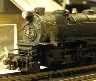
The next locomotive is a Bachmann Northern (4-8-4) a type the Pennsy never owned. The original idea was to use two of these models and attempt to create an N scale class T1 "Duplex" (4-4-4-4). The project started with the Bachmann's first generation of these units which are vastly different form the model shown here. I revised the idea and will use this as a basis for a class M1 "Mountain" (4-8-2) replacing the trailing truck with a PRR style single axle unit.

PRR Class L2s Mikado
On any other railroad this would've been a USRA designed 2-8-2 "light" Mikado. On the Pennsylvania it was a class L2s. American Locomotive built 5 of these for the GR&I (class GL1s) in 1919. The Pennsy acquired them and left them in their USRA configuration as evidenced by the lack of the trademark Belpaire firebox.

PRR Class L1s Mikado
The Pennsy version of the "heavy" Mikado type was the L1s class 2-8-2. The PRR owned 574 of these beasts (344 were built in the Juniata Shops at Altoona Works). They shared boiler and other components with the K4s. Like the K4s they served from 1914 to the end of steam in 1957. In the 1940's several were sold to other roads (AT&SF, L&NE, C&I, Interstate and DT&I). This model is a Kato mechanism combined with a GHQ L1s kit.

Potential PRR Class L1s Mikado
The Allegheny Eastern actually has two L1s class Mikado's. Southern Pacific 3303 is a Kato model of a USRA "heavy" 2-8-2. I have a GHQ L1s kit to convert this locomotive. The kit contains pewter parts to replace the Kato boiler, cab, tender and a few other parts. Hopefully the end result is a good looking, nice running model of an L1s.


PRR Class K4s
If there is one N scale locomotive that most modelers can recognize at a glance this is it. Mini-Trix has produced their version of the Pennsylvania class K4s almost as long as "N" has been a scale. The originals were cast metal, but this a newer plastic version. The shell is not as detailed or as faithful as the GHQ kit castings mentioned above or even the static Del Prado model. The wheel flanges are too deep for code 55 track so I had to grind them down. The mechanism in general is outdated so most modelers re-power or replace it totally. Prime candidate for donor is Kato's model of a Japanese class C-55 4-6-2.  If I had the money, I would use the GHQ kit on the Kato mechanism. For now this "de-motored" unit is used as a "dummy" helper on The Hill.

The Eye of the Beholder

The Camera Can't Lie
John Allen wrote quite a bit about model railroading and photography. He felt that photography could be used as a tool to enable a modeler to do better work. Case in point this photo of the GHQ/Kato Mikado I purchased at the Nashville train show. Whenever I look at it I perceive a thing of beauty. Yet as you can see the camera doesn't use a "rose colored lens". It sees what is really there. In this case it shows a very rough paint job, bent and missing handrails and a slight pitch to the cab roof. Even the running board are bent. I've looked at this model a dozen times and never even noticed the Keystone number board under the headlight. I've seen more in one glance at this photo then I have since I purchased the locomotive!
PRR Class L1s

Fortunately I didn't build this model so there is no "shame" about what a lousy job I did. The caboose to the left is an example of my own work. It's a Bowser model of a PRR NC5 "cabin car" or caboose. I did not build this model, but I did repaint it. I do all my painting with brushes and for some reason I cannot explain have never had trouble with brush marks (at least when using flat paint). I do have an air brush and can use it, but it's a lot of work to keep it clean and maintained. It's just easier for me to use paint brushes. Anyway, because I have such luck I'm hoping my own attempt at the second L1s comes out better. John was right. Seeing your models through the camera lens can be a valuable tool.

The New 5 x 8 Extension
The physical work of the expansion continues...I'm not sure how many model rails out there work like this. I wold love to be the kind of person who can plan this all out ahead of time but I'm not. To fall  back on John Allen again, he was allegedly able to plan so far ahead that even after two decades people were finding things he had built into his plans years ago. Of course John had quite a few "finished" (they are never finished) layout under his belt. I have built (or started to build) layouts before but nothing this extensive. The layouts were either smaller or the first sections of a larger layout.

I actually don't mind working like this even though it is probably counter intuitive to many people. I tried building layouts in sections, but the sections are more like dioramas. I have never been happy operating dioramas.

Foam Roadbed Cut to Fit Trackage
I had mentioned last time around that the "reverse cookie cutter" method is a lot of work. I believe I first saw this idea used to modify the Maryland & Pennsylvania layout in Model Railroader. (not sure what issue). They built the layout in phases. For the second phase they cut out the table top to match the revised track plan. For the Allegheny Eastern  I cut the extruded foam "table top" using a utility knife. I removed any foam that wasn't roadbed leaving only the portion that remains under the track work. Then I cut the 1/4" plywood "sub top". As I cut the roadbed out I'm finding that it probably isn't any more work than cutting the roadbed ahead of laying track. Either way you have this huge piece of plywood with a track plan on it. In the reverse method, it just a lot more obvious where the track goes. It also demands the use of hand tools so I don't risk damage my code 55 track. It would be easier to use a power jig saw with the tried and true method with no rails to crush. I personally Dislike power tools so either way I would be probably be using a hand saw. The saw I used is a smaller version of the Japanese pull saw I used to make benchwork. 
Using a Small Pull Saw Is Not as Much Work as It Seems.
They are both manual saws, but because of their razor sharp thin blades that cut very quickly. Actually meant for fine cabinetry they cut very accurately. I have also used them to shorten countertops in place, general framing work and undercut wall trim. I have even been able to trim paper thin adjustments on 2x4's. The resulting slices make great shims.

Mountain of Foam Will be Used to Make Foam Mountains
If there is a big drawback to any cookie cutter method it has to be waste. After all you start with a 4x8 sheet of plywood (or foam) and only use the part that actually hold up the track. One advantage to using thinner plywood is cost, both for initial purchase and the value of the wasted material. While the extra plywood may or may not be suitable for other projects, the extruded foam is a totally different story. The foam will be used to build up the surrounding landscape and make the basic structure of the Allegheny Mountains. I was a bit hesitant to just go out and purchase sheets of foam to create land forms. On some layouts the mountains are built from layers of 2" or deeper) layers of extruded foam. Only one home center around here carries such material and they charge $60 for 4'x8' sheet. I have some serious reservations about chopping up hundreds of dollars worth of extruded foam. The 1/2" thick foam I used goes for $11. I can live with that.
PRR Class AP20
I'll close with another model shot, this one of an AP20 set I working on. These are Kato models of Alco PA-1 units. The DGLE paint was brushed on and Micro-Scale decals were added. I then brushed on a coat of clear matte. I'm not happy with the decals (especially on the B unit) so I haven't added the clear plastic windows yet. Those stripes are extremely hard to apply and get perfectly straight without tearing. Believe it or not it is actually easier to stripe a full size object than a scale model!!! The bigger the object, the more room for tiny misalignments. In N scale even a fractional deviation appears HUGE. Once again, photographing the model highlights the flaws that need correction. These units will be redone until I get it right. After all, that's the way I'm building the whole layout.

Sunday, May 1, 2011

Serendipitous Procrastination

Ever noticed that sometimes procrastinating works out? You don't get to the store for a certain item and when you finally do it's on sale! I've seen it happen more than a few times, enough to make me wonder about whether getting it done right away is always the best way to handle some things. I'm not advocating procrastination. I just know that sometimes the creative process doesn't have a schedule.


Case in point..Altoona yard on the Allegheny Eastern. I had decided that since the real Altoona was so expansive, there was no way to replicate it in scale. As a result the yard I started to create was barely more than a staging yard. I didn't get far because it just wasn't what I wanted. The same thing happened with the East Altoona "extension" I was planning. Since I thought I didn't have space for the engine terminal I wanted on the layout I planned on building an extension over the workbench at the rear of the garage...
Original Track Plan With East Altoona Extension
Neither the extension nor the Altoona yard appealed to me much. The extension and workbench occupied a space that I felt could be better utilized. It also connected to the yard in a unworkable way. The yard itself wasn't what I wanted. There was also a problem with operations caused by the proximity of Gallitzin to Altoona. It just didn't work with only a foot of track between them. This was closely linked to the issue of the "flatland" table top required by the storage beneath. There simply was place to put the helix that elevating the trackage would require. The flat top also prevented the addition of respectable looking scenery below track level. I thought I could live with that, but you really  can't model mountain grades without having mountainside below the tracks.  I spent some time thinking of different ways to solve these problems.

I begrudgingly came to realize that the only way to gain more space between Gallitzin and Altoona was to bite the bullet and expand into the other half of the garage. This would solve that issue, and add additional storage room under the layout addition. There was still room for the motorcycle, the only vehicle we keep in the garage. Then, while surfing the web one day I came across a yard plan that looked like it could resolve some of the issues I have with the unfinished Altoona trackage. On his The White River & Northern web site Dave Smith shares the plan he created for Ridgeley Yard on Lee Weldon's Western Maryland Railway

Ridgeley Yard
The thing that caught my eye was the way Dave was able to split the yard into functional sections and incorporate the engine terminal into the space. I also like the way the main line bypasses the whole installation. There are a lot of similarities with what I had envisioned  but was not able to recreate.While I'm not sure I can use the design exactly as it appears I'm pretty sure I can adapt it. The first thing I did was flip it end for end so that the roundhouse sits at the "east" end of Altoona. I also did away with the industrial tracks. Dave's design also gives me some idea how to arrange turnouts to funnel traffic across the mains. I still have to work out how the passenger mains will pass to the "north" side of the yards.

Revising Altoona also requires widening the bench work in this area. Currently the benchwork is only two feet wide. Altoona shares this section with the mainline approach to Horseshoe. I've decided to increase this section to four feet (pretty standard everywhere else). This will provide the room necessary while keeping the overall width of the yard to the two foot maximum.

Expanded Layout
Expanding the layout allows me to turn Gallitzin 90 degrees. The extra space also creates room for a helix, enabling me to elevate the trackage west of Altoona. A double loop helix will be located west of Gallitzin, spiraling down under to emerge
All these changes will also necessitate relocating the Curve and its approach tracks two feet further "north". I plan to cut the table top using the "reverse cookie cutter" method. This basically means you cut the roadbed out after the track is layed. It's much more work than it would be than if I had planned ahead. There are some definite drawbacks to the evolutionary approach to layout planning.

I relocated the workbench to it's new location under the benchwork where the roundhouse will be. You can see on the plan that I used the open space to install a "beer" fridge and a storage cabinet. I have already begun the new bench work extension. I have also cut the extruded foam "subroadbed" to the actual track locations in the areas that will be elevated. Next step is to cut the 1/4" plywood table top to match. It will take a while, but it should allow me to remove whole sections of trackwork and relocate them according to the new plan.